SA_MAES4S_en.pdf - 第18页
18 4 T est and Change Device Parts It will measured with a Oscilloscope in a measurement range of 1 or 5 V olt per scale devision. cut length a b 7 6 1 2 3a 3b 4a 4b 5 Fig.20 Measurement by Oscilloscope Pulse sensor Carr…
17
4 Test and Change Device Parts
4.10.2 Check the Sensors on PCB
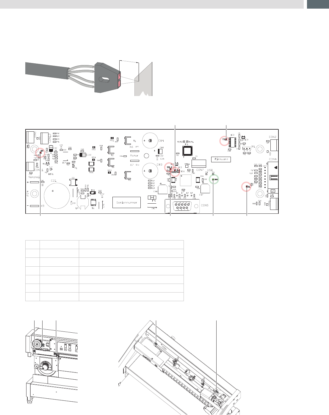
Some sensors are integrated into the Maestro 4S to control the function and operation of the device.
Thisarereexsensorswithaswitchreactionincaseasurfaceareinfrontofapprox.3mmdistance.
For changing and adjusting is a 5,5 mm jaw wrench necessary.
3mm
Fig.17 Reexsensor
To check the function of a sensor are checkpoints on the PCB integrated.
5
21
43
GND
Fig.18 Checkpoints to check the sensor function
Nr. Bezeichnung Sensor
1
SSR 2
carriage sensor right
2
TS
pulse sensor
3
RR
side sensor right
4
SSL 2
carriage sensor left
5
RL
side sensor left
GND
Ground
Table 3 Sensor - short description
4 1 32 5
Fig.19 Sensor position
18
4 Test and Change Device Parts
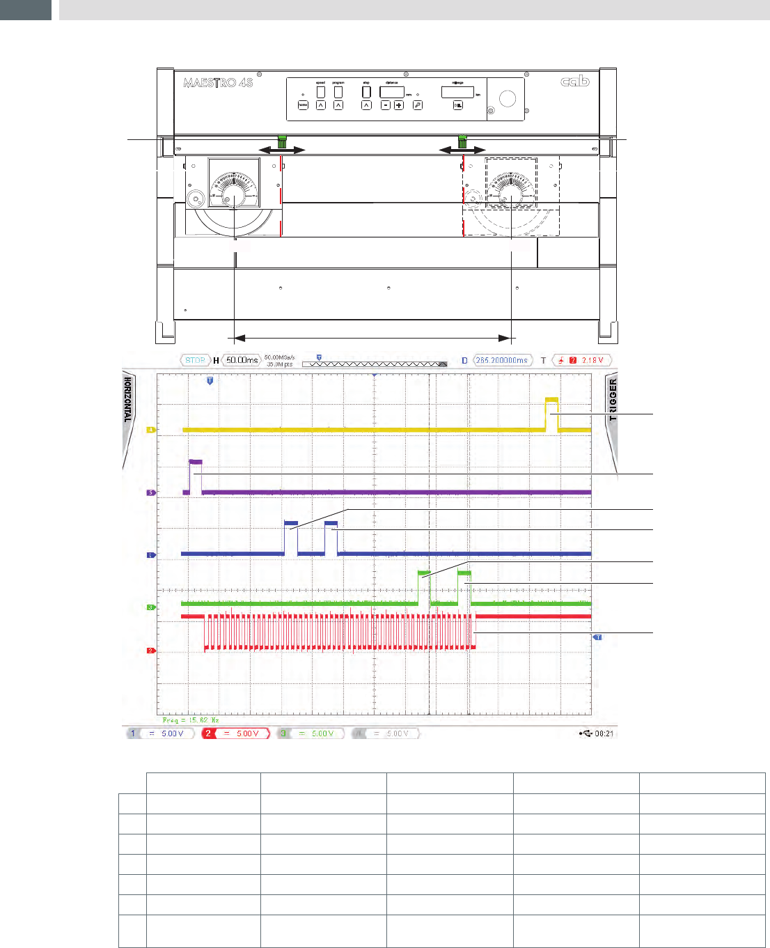
It will measured with a Oscilloscope in a measurement range of 1 or 5 Volt per scale devision.
cut length
a
b
76
1
2
3a
3b
4a
4b
5
Fig.20 Measurement by Oscilloscope
Pulse sensor Carriage sensor right Carriage sensor left Edge sensor right Edge sensor left
1
----------------------- ----------------------- ----------------------- End Position right -----------------------
2
----------------------- ----------------------- ----------------------- ----------------------- End Position Left
3a
----------------------- Cut stopper (6) ----------------------- ----------------------- -----------------------
2a
----------------------- ----------------------- Cut stopper (6) ----------------------- -----------------------
3b
----------------------- Cut stopper (7) ----------------------- ----------------------- -----------------------
4b
----------------------- ----------------------- Cut stopper 7) ----------------------- -----------------------
5
Start position to the
end of cut
----------------------- ----------------------- ----------------------- -----------------------
Table 4 Sensor peak 1. cut

19
Cause of error Effect / Display Error recovery
The food-switch is clear in the
moment of synchronization
LED not ready
Display step
Display distance
Display cut length
blink
Switch of the device and switch it on
again.
New synchronization
The device is switched on and the
carriage with the upper blade will
moved by hand out of the start position
The carriage with the upper blade
is blocked in operation.
LED not ready blink Press button home
Press the foot-switch and hold it
a Device will run into the start position
Clear the foot-switch
A new activation of the food-switch will
continue the program with a replay of the
last cut.
The food-switch will be clear if the
program is running.
Material is not separated after
program end
Switch of the device and make a new
synchronization .
Chang programing
- More cuts
- Reduce the distance between upper
and lower blade in smaller steps
Pulse sensor fault or wrong adjust Carriage moved short in one
direction and stopt with a jerk.
LED not ready blink
Sensor adjust or replace
Side sensor right/left fault or wrong
adjust
Carriage moved with full speed
on the side and stopt on the
mechanical end. It moved back
a short part and stoppt.
The same procedur like
"carriage or Blade are blocked".
LED not ready blink
Sensor adjust or replace
Carriage sensor right/left fault or
wrong adjust
In spite of other settings
moved the carriage over the
full distance of the possible cut
length.
The operation doesn't stop
and it will not shown an error
message.
Sensor adjust or replace
Table 5 Errors in operation and handling
5 Errors