SA_MAES4S_en.pdf - 第14页
14 4.7 Changing the Control Panel / Emergency Switch Danger! Danger to life and limb from power supply . Befor open the device unlink the power! 1 8 5 2 3 4 6 7 Fig.12 Dismount control panel / emergency switch 1. Dismo…
13
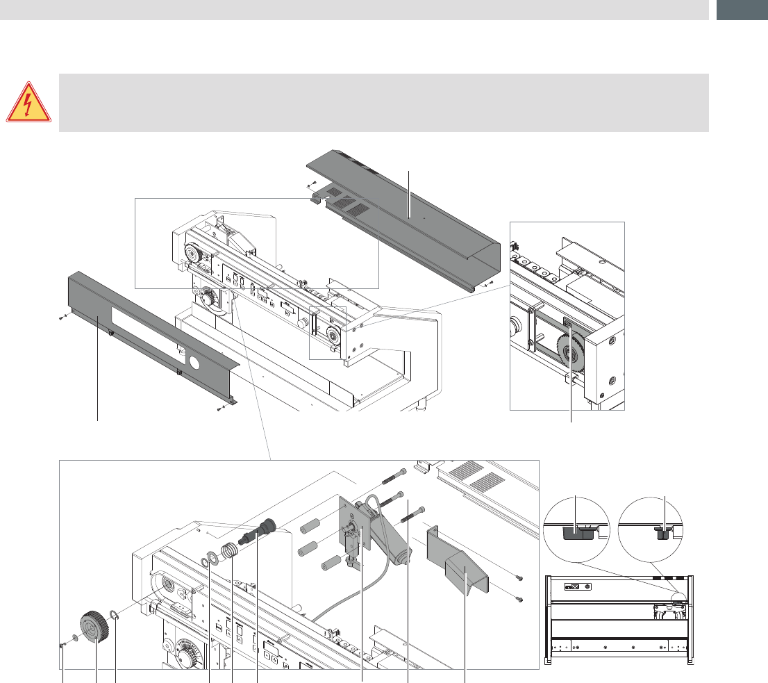
4.6 Changing the hub to main motor
Danger!
Danger to life and limb from power supply.
Befor open the device unlink the power!
4 5 6 7 8 9 121110
1
2
3
13a 13b
rear view
Fig.11 Dismount the hub to the main motor
1. Swing lever (13) in position b to connect the blade with the motor and to relax spring (8) .
2. Dismount front (1) and rear (2) cover.
3. Loosen the three screws (3) and move the tension wheel (5) to the center to relax the belt.
4. Loosen screw (4) and remove the belt gear (5) .
5. Dismount cooling bracket (12) .
6. Remover motor assembly (10) after loosening screws (11) .
7. Remove snap ring (6) with a snap ring caliper.
8. Pull out the hub (9) with spring (8), washer and snap ring (7) .
9. Remove snap ring (7) with a snap ring caliper and remove washer and spring (8) .
Mounting the new hub in reverse order.
4 Test and Change Device Parts
14
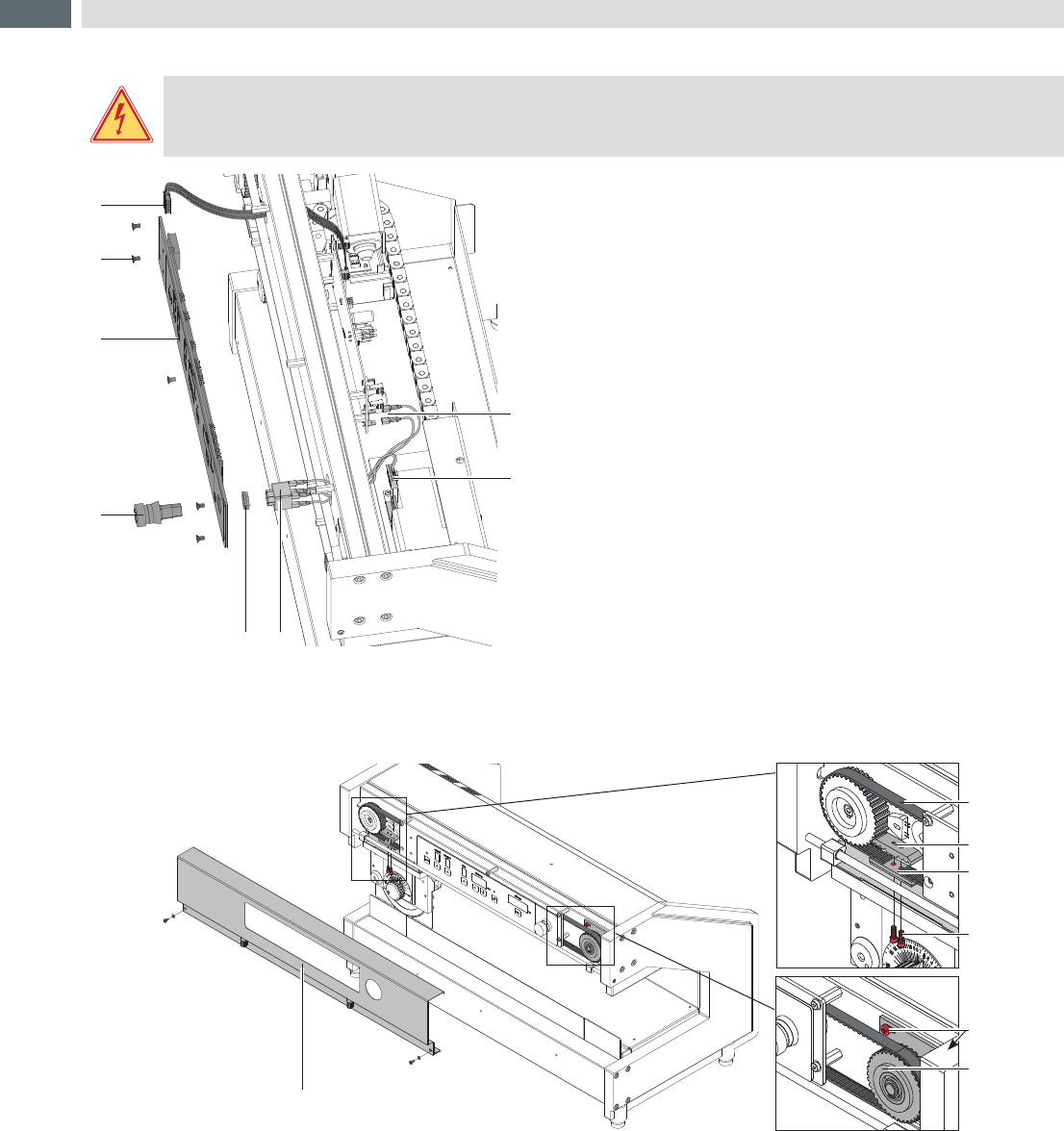
4.7 Changing the Control Panel / Emergency Switch
Danger!
Danger to life and limb from power supply.
Befor open the device unlink the power!
1
8
5
2
3
4
6
7
Fig.12 Dismount control panel / emergency switch
1. Dismount front and rear cover.
„Changing the hub to main motor“ on page 13
2. Pull out the connector (3) on the power supply to the
emergency switch.
3. Pull both Push-on-contacts (7) on the PCB to the
emergency switch.
4. Loosen screws (2).
5. Pull out connector (1) on the control panel (3).
6. Turn the lower part of the emergency switch (6) short only
approx. 10° and remove it.
7. Loosen nut (5) and remove the upper part (4) of the
emergency switch.
Mounting of the control panel (3) / emergency switch in
reverse order.
4.8 Changing the Belt
1
2
3
4
5
6
7
Fig.13 Changing the belt
1. Dismount front cover (1).
2. Loosen the three screws (6) and move the tension wheel (7) to the center to relax the belt (2) .
3. Loosen screws (5) and remove the upper catch plate (3).
4. Change the belt (2) and put it over the tension wheel and belt gear.
5. Put in the belt (2) so that the ends are between the lower catch plate (4) upper catch plate (3). but the both screw
holes must be free.
6. Put in screws (5) and tighten it.
7. Move the tension wheel (7) to th right side (outside), tension the belt (2) and tighten screws (6).
8. Mount the front cover (1).
4 Test and Change Device Parts
15
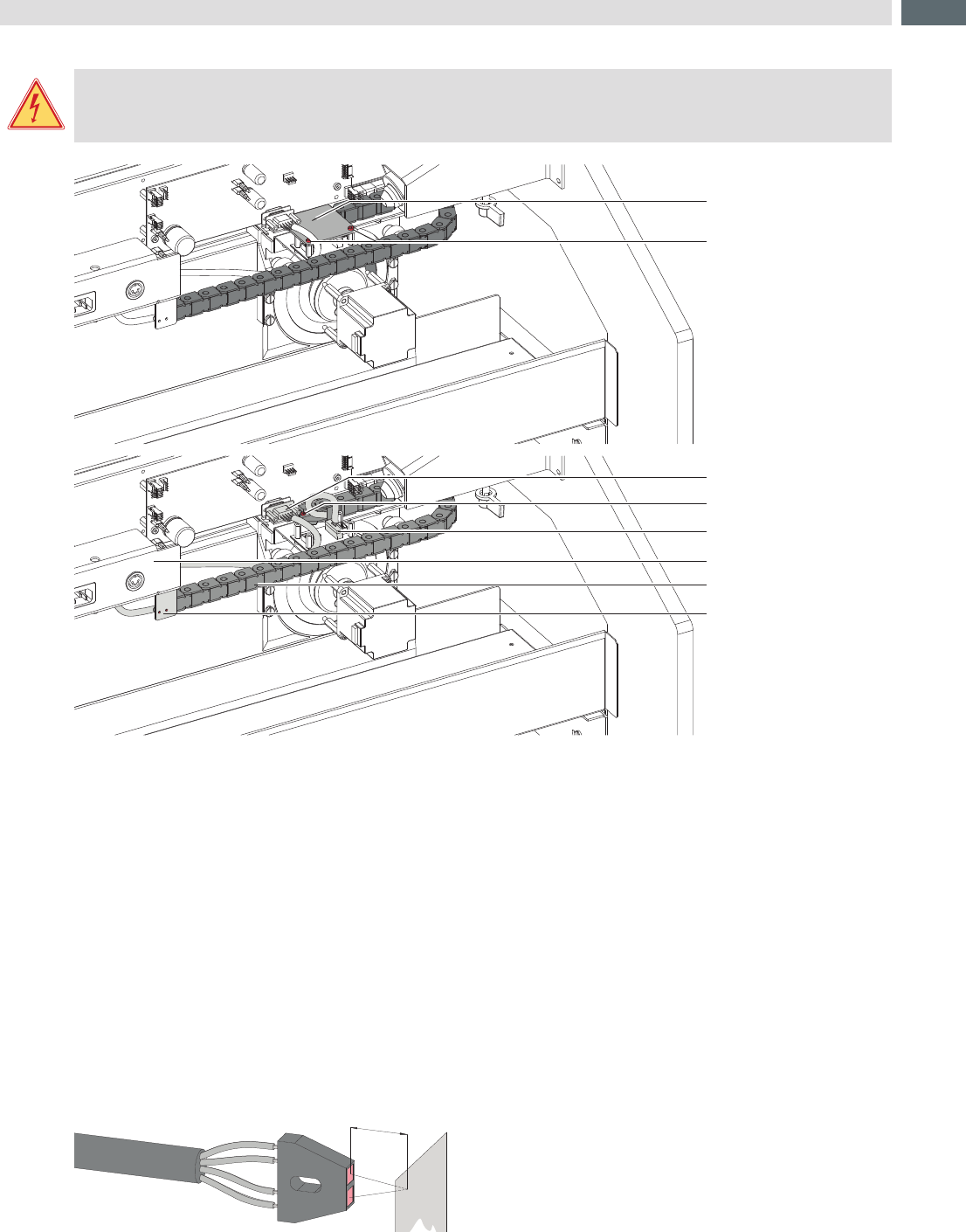
4.9 Changing the Energy Track
Danger!
Danger to life and limb from power supply.
Befor open the device unlink the power!
5
7
6
8
4
3
2
1
Fig.14 Energy track mount / dismount
1. Dismount the rear cover. Page 13
2. Loosen screws (2) and remove PCB cover (1) .
3. Pull connector (3 and 4) and put out the cable from the cable retainer on the power supply (7) .
4. Loosen screws (4) and (8) .
5. Remove the energy track (7) .
Mounting the energy track (7) in reverse order.
4.10 Check the Sensors
Some sensors are integrated into the Maestro 4S to control the function and operation of the device.
Thisarereexsensorswithaswitchreactionincaseasurfaceareinfrontofapprox.3mmdistance.
For changing and adjusting is a 5,5 mm jaw wrench necessary.
3mm
Fig.15 Reexsensor
4 Test and Change Device Parts