SA_MAES4S_en.pdf - 第7页
7 3 Overview 3.1 Views without covers and cable 11 9 12 10 1 2 6 5 4 3 14 15 16 13 7 8 1 Belt Gear Main Motor 9 Control Panel 2 Pulse Sensor 10 Emergency Switch 3 Carriage Sensor right / Links 11 tension Wheel 4 Carriage…
6
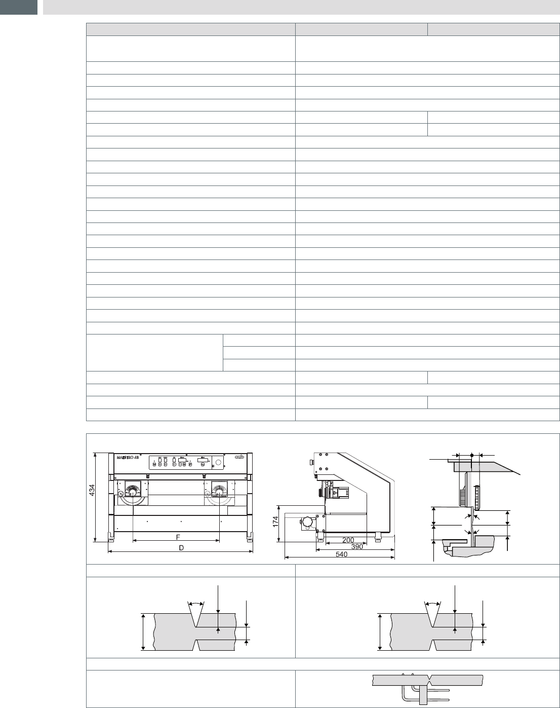
2 Technical Data
Technical data 4S/450 4S/600
Separation type Component side:
Soldering side:
circular blade
linear blade
Operation motorized and optimized
Separation speedt 300/500 mm/sec. switchable
Material FR4, Aluminium
Height of components Component side/Soldering side up to 34 mm
Cutting length , continuous F up to 450 mm up to 600 mm
Length D 702 mm 852 mm
Depth storage table 200 mm
Programming
Home Request drive to starting position, Acknowledge
Speed H (High): 500 mm/Sek.
L (Low): 300 mm/Sek.
Program 9
Step (cutting steps) 1 – 5
Distance (between blades) 0,9 mm bis 0,05 mm
Key switch button Release of programming
Mileage (Kilometer counter) up to 99 km
DEL Reset of the kilometer counter
Power switch ON/OFF
Foot switch START Separation
Safety switch Emergency stop
Spannung 100–240 V~ 50/60 Hz
Emission sound pressure level LpA < 70 dB (A)
Temperature / humidity not
condensing
Operation +10–35°C / 10–85%
Stock 0–60°C / 20–80%
Transport -25–60°C / 20–80%
Weight 38 kg 46 kg
Height/Depth 434x425 mm
Width 702 mm 852 mm
Approvals CE, FCC class A
Dimension Maximum Height of components on the cut nut
27 21,5
3434
400...40
10˚
10˚
Enlargement of the PCB outside after separation. typical 0,2 mm
30˚
FR 4
0,8-3,2
min. 0,25
max. 0,8
30˚
Alu
0,8-1,5
min. 0,25
max. 0,3
The cut nut could be broken by a cutout.
In case of overlaying components, the linear blad
must be hollowed.
If required request.
Table 1 Technical data
7
3 Overview
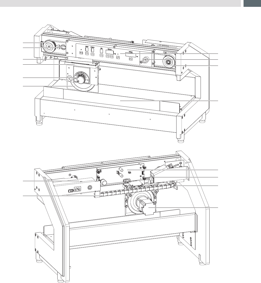
3.1 Views without covers and cable
11
9
12
10
1
2
6
5
4
3
14
15
16
13
7
8
1 Belt Gear Main Motor 9 Control Panel
2 Pulse Sensor 10 Emergency Switch
3 Carriage Sensor right / Links 11 tension Wheel
4 Carriage 12 Linear Blade
5 Set knob for cutting depth 13 PCB Control
6 Upper Circular Blade 14 Main Motor
7 Power Supply 15 Clutch Main Motor
8 Energy Track 16 Motor Circular Blade
Fig.1 Frontview
Fig.2 Rearview
8
3 Overview
3.2 Tools
Do not use any worn of damaged tools.
Only use tools and testing devices that are suitable for the task at hand.
Special tools (cab production):
• Dial gauge assembly (cab part No. 8970208) to check the blade position
Commercial tools:
• Allen key 1,5, 2,0, 2,5, 5,0 mm
• Jaw wrench 5,5 mm
• Phillips-head screwdriver, size 1
• Precision Snap Ring Caliper A0
• Precision Snap Ring Caliper A1
• Oscilloscope
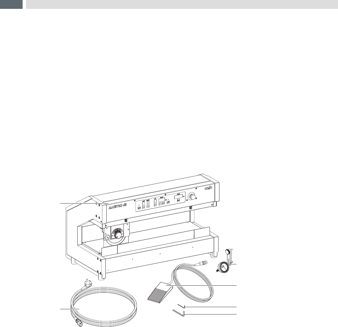
3.3 Contents of Delivery
5
6
4
2
1
3
1 Maestro 4S/300 (600)
2 Power Cable
3 Dial Gauge Assembly
4 Food Switch
5 Hexagonal Wrench
DIN911 2mm
6 Hexagonal Wrench
DIN911 5mm
Documentation
Fig.3 Contents of Delivery