00196624-04_Service Manual WPC5_6_EN_01-2019.pdf - 第10页
Service Manua l WPC5 / WPC6 Page 3- 10 3 Replacing Spare Parts 3.1 Safety Instru ctions WARNING Consider the Safet y Instructions Nonobservance of these safety instructions may cause injury to personnel and da mage to …
Service Manual WPC5 / WPC6
Page 2-9
2.2 What To Do Before Starting Servicing Work...
Switch off the machine and secure to prevent unauthorized reactivation
➢ End all placement operations on the machine.
➢ Disconnect the changeover table of the gantry concerned, if necessary.
➢ If necessary, move the gantry to the service position.
➢ End and close all programs and the operating system. Wait until the operating system has
shut down completely.
➢ Switch the placement machine off at the main power switch.
➢ Disconnect the machine from the power supply.
➢ Disconnect the placement system from the compressed air supply.
➢ Switch off the motor protection switch in the power supply and secure the operating lever
with a padlock.
The tag out alternative
If a machine can be locked, it must be. However, there are situations where energy isolating
devices cannot accommodate locks. In these cases, the energy isolating devices must be
tagged to warn employees that the machine is de-energized for servicing. The tag must be
securely fastened, it must be placed in a position visible to all and it may only be removed by
the person who attached it..
CAUTION
! Caution when moving gantries !
When moving a gantry, the placement head can be damaged.
When moving the gantry, observe the following:
➢ NEVER move the gantry by pushing with your hands against the Collect&Place head.
➢ NEVER push the gantry while the Z axis is lowered.
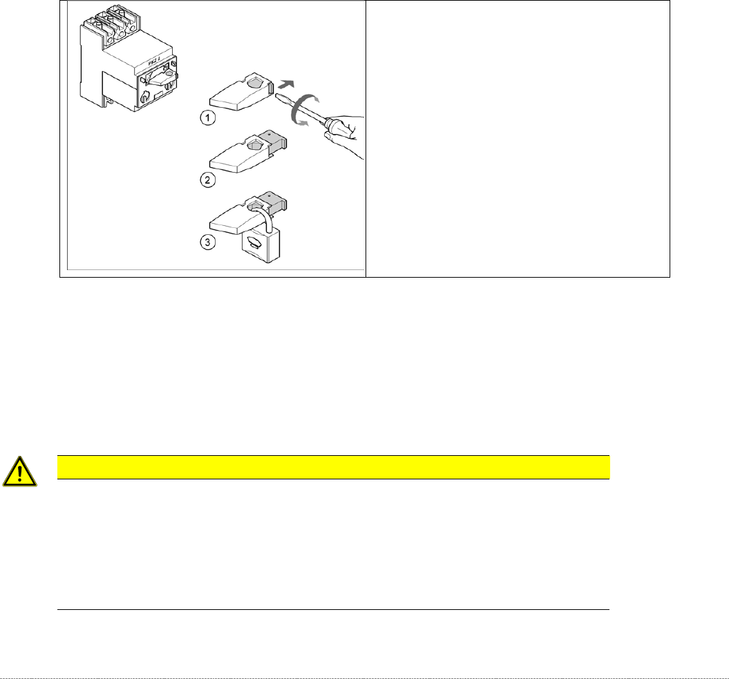
➢ Turn the operating lever (1)
counterclockwise.
➢ Use the screwdriver to push the locking
lug (2) out of the operating lever (1).
➢ Secure the operating lever with a padlock
(3).
Service Manual WPC5 / WPC6
Page 3-10
3 Replacing Spare Parts
3.1 Safety Instructions
WARNING
Consider the Safety Instructions
Nonobservance of these safety instructions may cause injury to personnel and damage to the
machine!
The service work described in this manual may only be performed by specially trained service
technicians, with appropriate qualifications and expertise.
➢ Observe the safety instructions in the SIPLACE SX operating manual and those for the waffle-
pack changer (WPC), during all service work.
CAUTION
Never open screws with locking varnish
If screws sealed with locking varnish are opened, the assembly concerned will require extensive
readjustment.
➢ Only loosen screws sealed with locking varnish if the instructions in this manual explicitly ask
you to do so.
➢ If you open screws sealed with locking varnish without express instructions to do so, the WPC
must be taken to ASM for readjustment.
Preparations for service work
➢ Finish all placement operations at the SIPLACE machine.
➢ Switch the WPC off at the main switch.
➢ Carefully move the WPC out of the SIPLACE machine.
➢
Disconnect the WPC from the power supply.
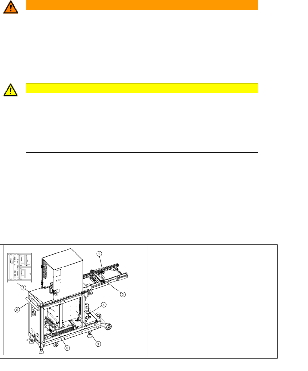
3.2 Overview of the main assemblies
Overview
1. Feed axis
2. Drive unit – feed axis
3. Lifting axis with tower
4. Drive unit – lifting axis
5. Power Supply Unit
6. Non-stop module (WPC6 only)
7. Control unit (position when fitted)
Service Manual WPC5 / WPC6
Page 3-11
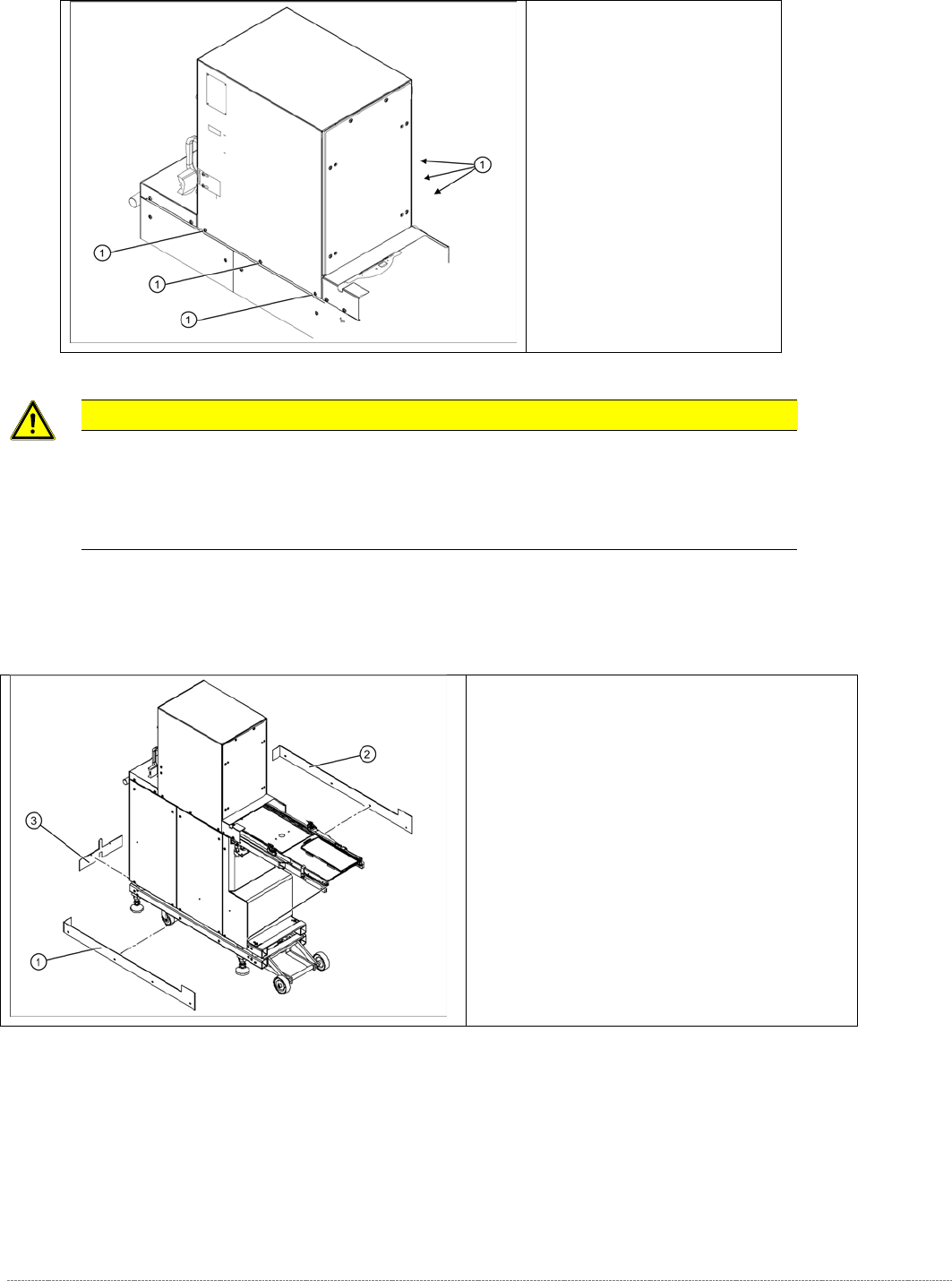
CAUTION
! Not open screws with locking varnish !
The tower is set with these 6 screws (1) at the factory.
If you open these screws, the WPC has to be readjusted by SIPLACE Service, or taken back to
ASM for repair.
Screws sealed with locking
varnish on tower.
Bottom cover plates
If the WPC is configured for high machine
heights, additional cover plates will be attached to
the base.
1. right-hand cover
2. left-hand cover
3. front cover
You may need to remove these covers before
performing service work.