00196624-04_Service Manual WPC5_6_EN_01-2019.pdf - 第65页
Service Manua l WPC5 / WPC6 Page 3- 65 3.6.5.3 Repla cing the In rush Current L imitat ion Board The inrush current limi tation boards are locate d at the back of the e lectrical unit (see "3.6. 4.2 Power Supply f…
Service Manual WPC5 / WPC6
Page 3-64
3.6.5.2 Replacing the Emergency STOP and Protective Door Monitor (WPC6 only)
Spare Part
• Emergency STOP and guard door monitor [03056745-xx]
Removal / Installation
➢
➢
➢
➢
➢
➢
➢
➢
➢
➢
➢ Label all connections for easier installation later.
➢ Unplug all connections from K5/K6.
➢ Lever the K5/K6 off the mounting rail.
➢ Connect the new K5/K6 to the mounting rail and restore the electrical connections.
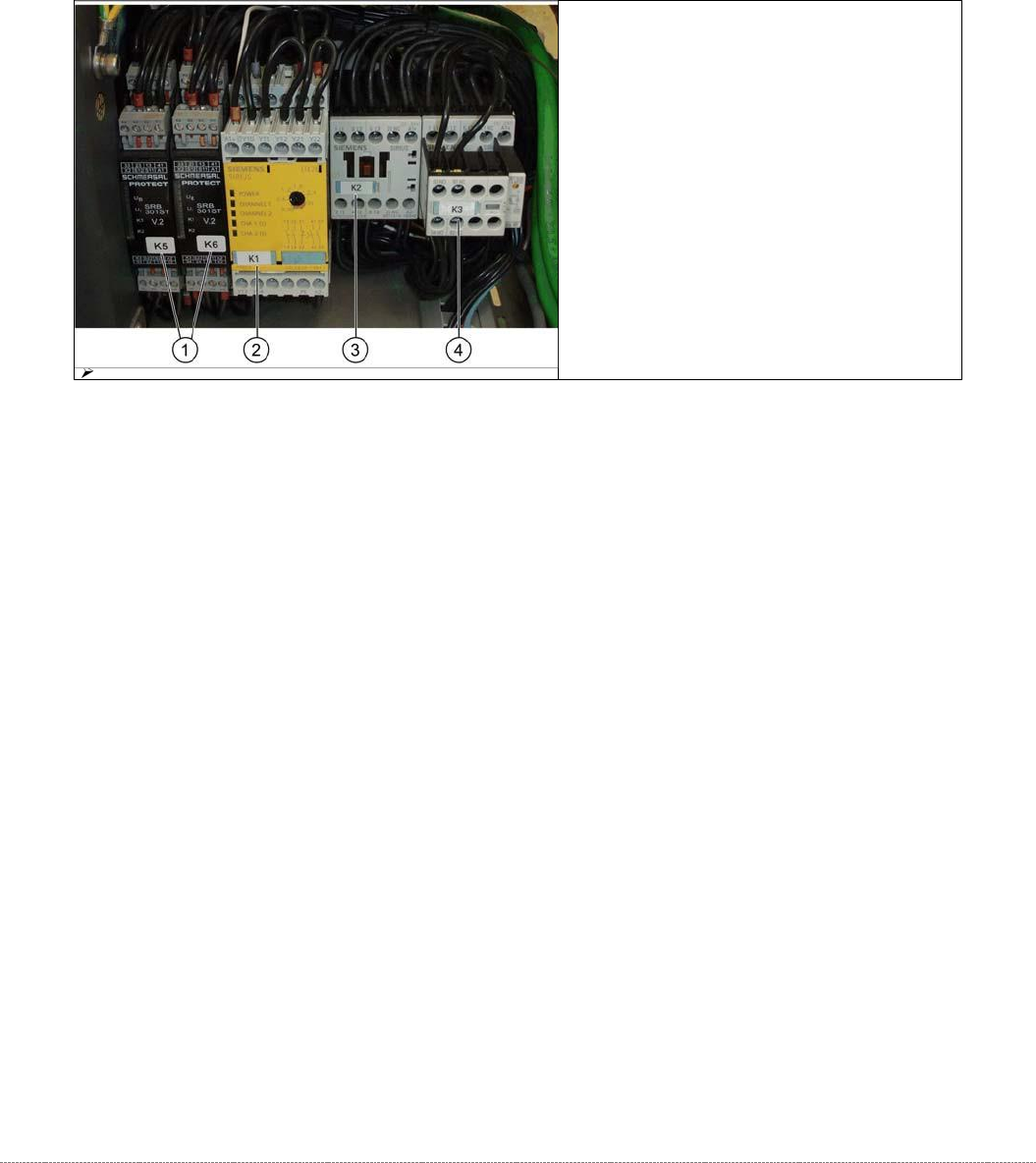
1. Protective door monitor and
emergency STOP, K5 and K6
2. SSK K1
3. Contactor K 2
4. Contactor K 3

Service Manual WPC5 / WPC6
Page 3-65
3.6.5.3 Replacing the Inrush Current Limitation Board
The inrush current limitation boards are located at the back of the electrical unit (see "3.6.4.2
Power Supply for WPC5" [➙
3-60] for WPC5 and "3.6.4.3 Power Supply for WPC6" [➙ 3-61] for
WPC6).
Spare Part
• Inrush current limitation board WPC [03047752-xx] (A1)
• Inrush current limitation board WPC NS [03056232-xx] (A2) (WPC6 only)
Removal / Installation
➢ Label all connections for easier installation later.
➢ Unplug all connections from the inrush current limitation board.
➢ Lever the inrush current limitation board off the mounting rail.
➢ Connect the new inrush current limitation board to the mounting rail and restore the
electrical connections.
Settings
• No settings are required.
See also...
@
3.6.5
Power Supply electric [➙ 3-63]
Service Manual WPC5 / WPC6
Page 3-66
3.6.5.4 Replacing the Complete Power Supply Unit
Spare Part
• WPC5 power supply unit [03072955-xx]
• WPC6 power supply unit [03056701-xx)
Overview
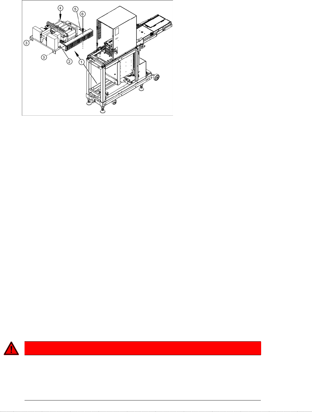
The power supply assemblies (1), such as the transformer, relays and contactors, inrush current
limitation board etc. are fitted on an mounting plate (2) and can be removed as a complete unit.
The mounting plate is fixed with 4 screws to the WPC frame:
• 2 x side, front (3)
•
1 x on frame, left side (4)
•
1x on frame, right side - in cable duct (6)
Removal
➢ To gain better access to the power supply unit, dismantle the side covers and, if necessary,
the front cover. See section.
➢ Check whether all cables are labeled.
➢ Make sure that you are able to correctly assign all cables and plugs again. Where
necessary, label cables, plugs and connections for easier reconnection later.
DANGER
Voltage at cable to the main switch
When the WPC power cable is connected and the main switch has been turned off,
voltage is still present at the cable to the main switch, at the line filter and at the terminals
to the main switch.
Disconnect the WPC from the power supply.