00196624-04_Service Manual WPC5_6_EN_01-2019.pdf - 第113页
Service Manua l WPC5 / WPC6 Page 4-113 NOTICE Calibrating with the Gauge Base Plate Due to higher accuracy and stability , it is recommended to use the „Jig for WPC4 - 6 base plate“ [03073064 -01] , instead of the norm…
Service Manual WPC5 / WPC6
Page 4-112
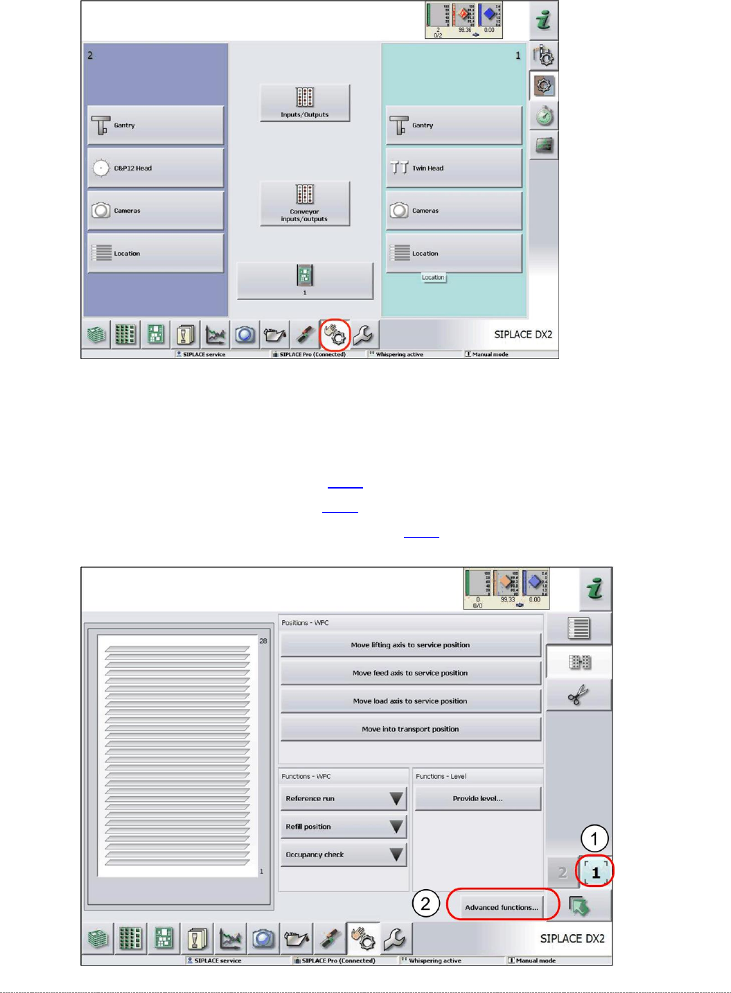
➢ Select the required location (1). (location 1 in this example)
➢ Select the
Advanced functions
button.
The relevant axis can be selected in the following view.
See:
• "4.1 Calibrating the Lifting Axis"
[
➙
4-114]
• "4.2 Calibrating the Feed Axis" [
➙
4-123]
• "4.3 Calibrating the Load Axis (WPC6 only)" [
➙
4-132]

Service Manual WPC5 / WPC6
Page 4-113
NOTICE
Calibrating with the Gauge Base Plate
Due to higher accuracy and stability, it is recommended to use the
„Jig for WPC4-6 base plate“ [03073064-01],
instead of the normal waffle-pack tray carrier (WPTC) plate,
for all the following calibration steps.
Service Manual WPC5 / WPC6
Page 4-114
4.1 Calibrating the Lifting Axis
➢ Before calibration, remove all waffle-pack tray carriers (WPTCs) from the WPC.
Calibration of the lifting axis consists of the following functions:
• "4.1.2 Teaching the Zero Point Position" [
➙
4-115]
• "4.1.3 Reference Proximity Switch (Bero)" [
➙
4-118]
• "4.1.4 Calibrating the Limit Switch" [
➙
4-119]
• "4.1.5 Teaching the Load Axis Offset Point" [
➙
4-120]
4.1.1 Requirements for Settings
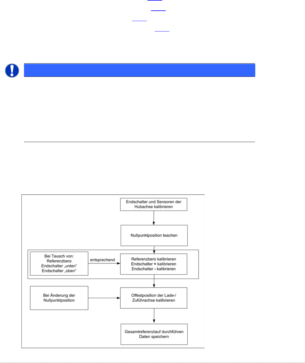
Lifting axis – order of settings
If the limit switches or sensors are replaced, you will need to recalibrate or reset these
accordingly.
A complete recalibration is only needed if the zero point position is changed
NOTICE
Crash Light Barrier Component Height
The crash light barriers for height checks must not trigger during calibration.
During calibration of the reference sensors and the limits switches, make sure that the
crash light barriers do not trigger without good reason. If this does happen, the
calibration process will stop and no values or invalid values will be calculated..
➢ During calibration, make sure that the light beam of the crash light barriers is not interrupted by
objects etc...