00196624-04_Service Manual WPC5_6_EN_01-2019.pdf - 第56页
Service Manua l WPC5 / WPC6 Page 3- 56 Settings ➢ Check that the sensors have a correct cab le assignment. ➢ To do this, open the stat ion software menu at: ⇨ Manual Ope rations ⇨ Subs ystems ⇨ WPC ⇨ Inputs/Outputs . ➢…
Service Manual WPC5 / WPC6
Page 3-55
Installation
➢ During installation, make sure you fit the parts in the correct position (front/back).
➢ Carefully lift the new control unit onto the threaded pins and fix in place with the 4 nuts.
➢ Restore all electrical connections and plug in the ground cable (1) again.
➢ Run the cables neatly inside the control unit (3) so that they do not interfere with any other
parts.
➢ Fasten the cable with cable ties.
➢ Fit the plexiglass cover..
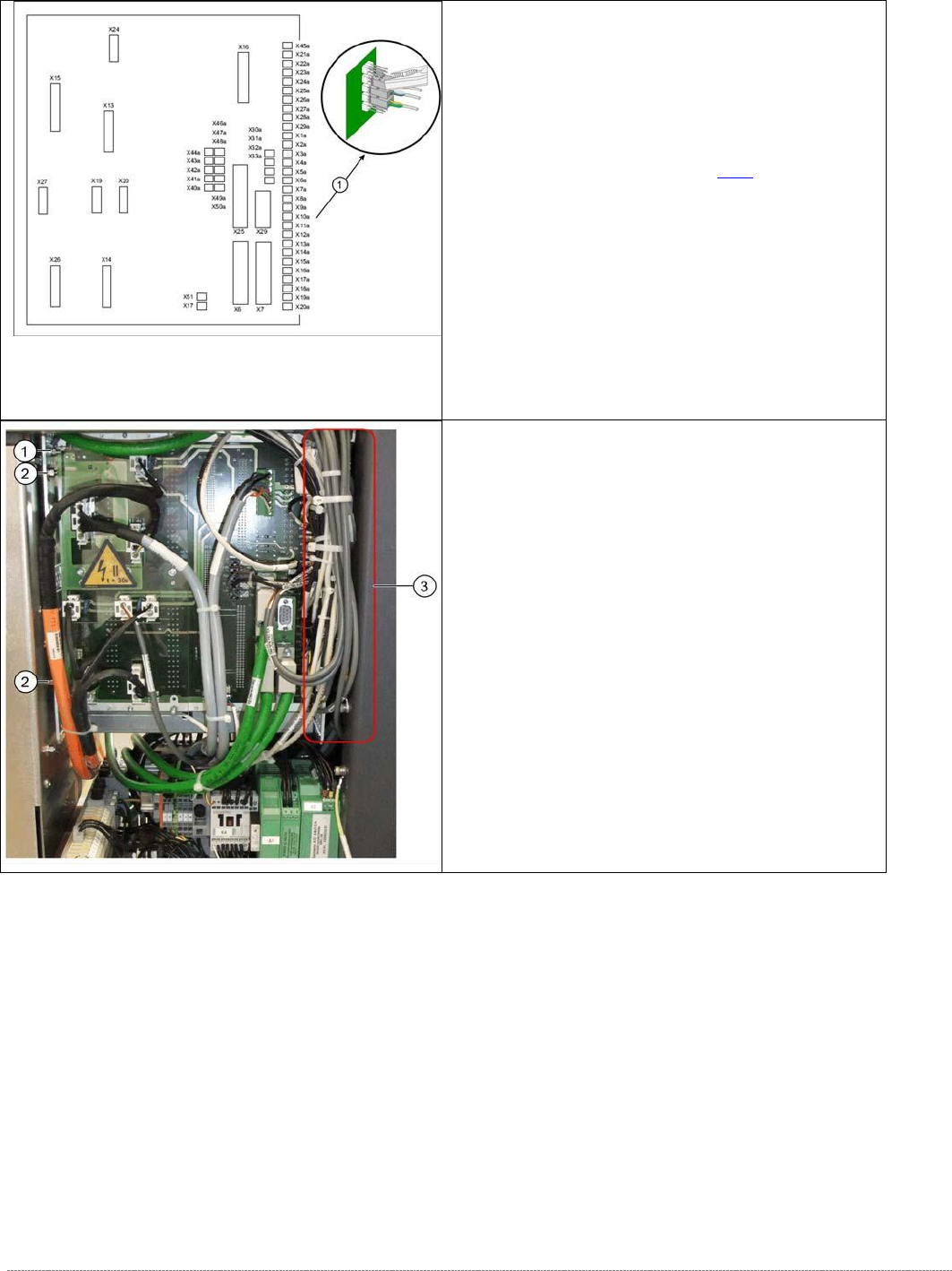
Control unit back plane - details
1. Connections for limit switches, sensors and light
barriers.
For a detailed overview of the connections, see
"3.7.1.3 Detailed Connections for Limit Switches,
Sensors and Light Barriers" [➙
3-71].
➢ Carefully unplug connections X1A to X20A on
the terminal strip (proximity switch, sensors etc.)
with a suitable pair of pliers (e.g. combination
pliers) (1). Make sure that you do not bend the
contact pins.
➢ Unplug the remaining cables, plugs and
connections.
Control unit back side – example WPC6
➢ Disconnect the control unit ground cable (1)
from the WPC frame.
➢ Loosen the two nuts (2) from the threaded pins
on the control unit located on the back plane
side.
➢ Loosen the two cap nuts from the threaded pins
on the front side of the control unit.
➢ Carefully pull the control unit out towards the
front.

Service Manual WPC5 / WPC6
Page 3-56
Settings
➢
Check that the sensors have a correct cable assignment.
➢
To do this, open the station software menu at:
⇨ Manual Operations ⇨ Subsystems ⇨ WPC ⇨ Inputs/Outputs.
➢ Trigger the individual limit switches and sensors manually, to check whether the correct
input is activated.
NOTICE
Machine data and calibration
If you have also replaced the controller board or axis card, together with the control unit,
you will need to perform a firmware download (BIOS and application).
If there are no current machine data (*.xml) available, you will need to perform full
calibration of the WPC.
Service Manual WPC5 / WPC6
Page 3-57
3.6.3.9 Replace the Fan
Spare Parts
• Axial fan [00319141-xx]
Overview
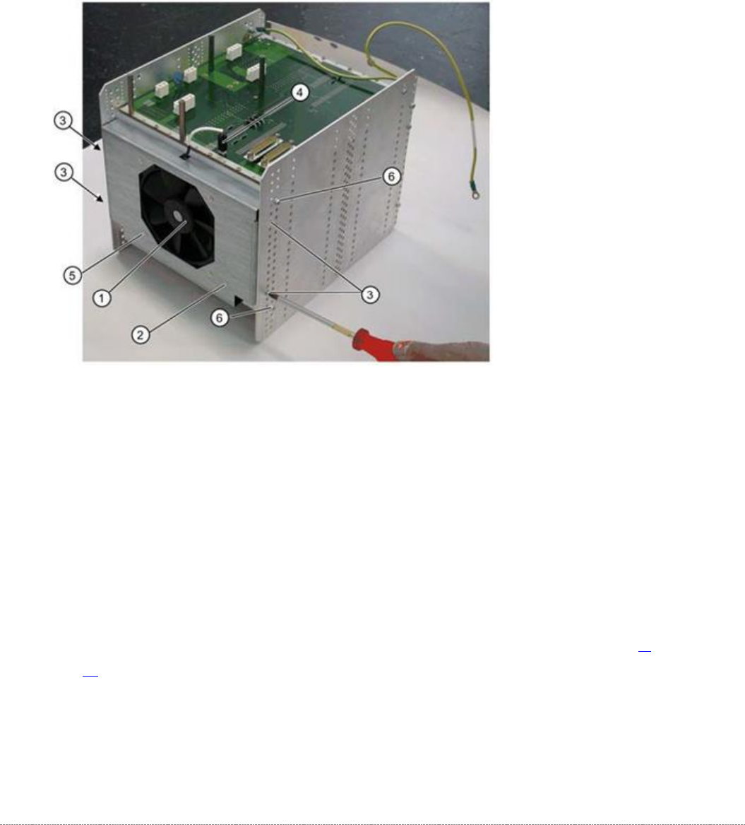
The fan (1) is located on the underside of the control unit and is fitted with the help of a mounting
frame (2).
1.
Fan
2. Mounting frame
3. 4 x mounting frame fastening screws
4. Electrical connection for fan
5. 4 x fastening screws for fan on mounting frame
Removal
➢ Dismantle the complete control unit (see "3.6.3.8 Replace the Complete Control Unit" [➙ 3-
54]).
➢ Unplug the connection cable (4) and the backplane X17.
➢ Mark the installation position of the mounting frame (2) on the relevant control unit holes.
➢ Loosen the 4 fastening screws (3) on the mounting frame (2).
➢
The mounting frame (2) can be levered more easily out of the holes, if you also loosen the 2
screws (6) on the control unit.