Apollo1_Operators_Manuel.pdf - 第112页
B- 112 cab - Produkttechnik GmbH / Tharo Systems, Inc. Appendix B - Pin Assignment of the Interface Connectors Pin Assignment of the Serial Interface Connectors The Apollo provides a 25 pin SUB-D connector for the serial…

A-111cab - Produkttechnik GmbH / Tharo Systems, Inc.
B-112 cab - Produkttechnik GmbH / Tharo Systems, Inc.
Appendix B - Pin Assignment of the Interface Connectors
Pin Assignment of the Serial Interface Connectors
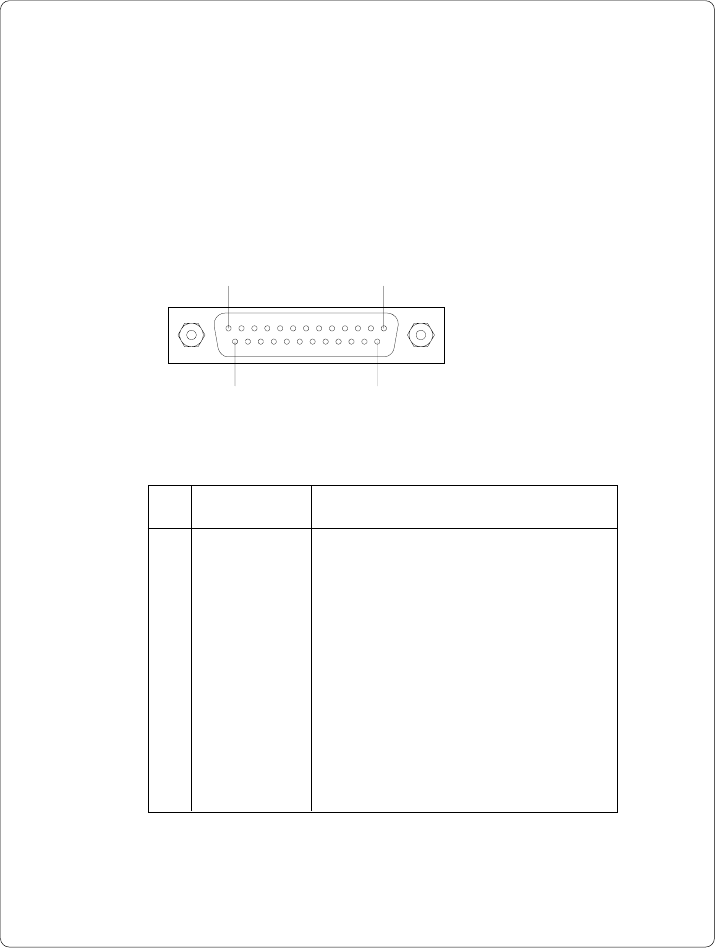
The Apollo provides a 25 pin SUB-D connector for the serial interfaces which are
internally available, i.e. RS-232, RS-422 and RS-485.
Pin 1Pin 13
Pin 14Pin 25
Fig. B-1 Connector of the serial interface (rear of the printer)
Table B-1 Signals of the serial interface connector
Pin Signal Function
1 CG Protective grounding
2 TxD Transmit data (RS-232)
3 RxD Receive data (RS-232)
4 RTS Request to send
5 CTS Clear to send
7 GND Logic grounding
9 TDATA+ Transmit data (RS-422, RS-485)
10 TDATA- Transmit data (RS-422, RS-485)
18 RDATA+ Receive data (RS-422, RS-485)
19 RDATA- Receive data (RS-422, RS-485)
20 DTR Data terminal ready
B-113cab - Produkttechnik GmbH / Tharo Systems, Inc.
Interface Cable for RS-232
The following chapter shows some typical RS-232 interface cable configura-
tions. Note, that the pin assignment may vary for different computers. If you
have any problems with the connections, contact the manufacturer of your
computer on the pin assignment of the interface. Use the pin assignment of
the printer as shown in Table B-1 to obtain a suitable cable.
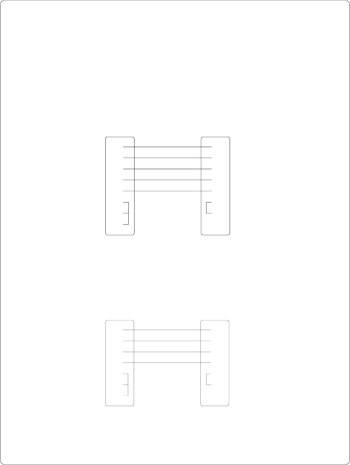
PC Apollo
25 pin connector 25 pin plug
PC Apollo
9 pin connector 25 pin plug
22
33
57
820
14
45
6
Fig. B-3 Interface cable with 9 pin computer connector
for RS-232 with protocol " ---" or "XON/XOFF"
Fig. B-2 Interface cable with 25 pin computer connector
for RS-232 with protocol " ---" or "XON/XOFF"
11
23
32
520
77
64
85
20