Apollo1_Operators_Manuel.pdf - 第35页
35 cab - Produkttechnik GmbH / Tharo Systems, Inc. Adjustment of the Printhead Support 4 2 4 1 1 Apo llo 1 Ap oll o 2/3 Fig. 7 b Adjustment of the printhead support When printing narrow labels (width less than 2.5 in or …
34 cab - Produkttechnik GmbH / Tharo Systems, Inc.
7 Adjustments Concerning the Labels
Adjustment of the Label Edge Sensor
2 1
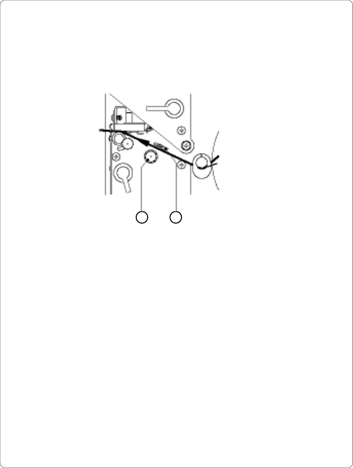
Fig. 7 a Adjustment of the label edge sensor
To accommodate a variety of print jobs, the position of the label edge sensor
(1) can be adjusted at right angles to the path of the paper feed. This setting is
particularly useful if the required labels are either narrow, or have punch holes or
reflective markings, or deviate from the square or rectangular shape.
It is important to ensure that the sensor is positioned in a way that the gaps
between the labels or the markings can be recognized by the photocell. (the
position of the sensor is marked by a notch in the sensor holder)
If using labels with an unconventional shape (i.e. round or curved), the sensor
should be positioned at the front edge of the label.
Adjust the sensor position using the knurled knob (2).
By turning the knob clockwise the sensor moves outwards, and by turning the
knob counter-clockwise the sensor moves inwards.
35cab - Produkttechnik GmbH / Tharo Systems, Inc.
Adjustment of the Printhead Support
4
2
4
1 1
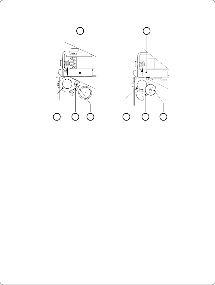
Apollo 1 Apollo 2/3
Fig. 7 b Adjustment of the printhead support
When printing narrow labels (width less than 2.5 in or 60 mm), it is possible that
the printhead will come into direct contact with the drive roller. This will lead to
premature wear on the printhead. In addition, the printhead will be at a slight
angle to the label, thus, the uneven pressure may result in an inconsistent
image density from one edge of the label to the other.
To correct this problem, the printhead support (2) may be adjusted.
Adjust printhead support as follows :
1. Loosen the locking screw (2). For Apollo 1, this screw is an oval-headed
screw, whereas for Apollo 2/3 it is a knurled screw.
2. Move the locking screw (2) as required within the adjustment slot (3). This
will cause the cam shaped printhead support (4) to rotate, in effect,
providing a higher or lower base on which the printhead mounting (1) rests.
As the adjustment criterion, check the quality of the print image.
3. Tighten the locking screw (2).
3 3
2
36 cab - Produkttechnik GmbH / Tharo Systems, Inc.
Adjustment of the Transfer Ribbon
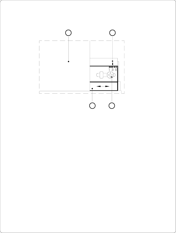
Fig. 7 c Adjustment of the transfer ribbon
If creases, lines or black patches appear in the print image resulting in a poor
print quality, this may be caused by wrinkles in the transfer ribbon (1). To
remove the wrinkles, the tension of the ribbon should be made even from the
left to the right by moving the ribbon shield (4) up or down.
1. Loosen the adjustment screw (3).
2. Shift the transfer ribbon shield (4) sideways into the direction of the wrinkle.
Moving it to the left will increase the tension on the left.
Use the scale (2) provided to monitor the adjustments made. If the screw
is in position "1", the tension is highest on the outside, and if it is in position
"5", the tension is highest on the inside.
3. After completing the adjustment, tighten the securing screw (3).
1 2
34