00194705-0102_AI_1WireBus_DE+EN.pdf - 第45页
Retrofit instructions: New 1-wire wiring for the SIPLACE X-series 11/2005 Edition 45 2.4 Part s required 2 2 2.4.1 T ools and consumables required Set of hexagon socket span ners 2 Set of screwdriv ers 2 Set of diagonal …
Retrofit instructions: New 1-wire wiring for the SIPLACE X-series
11/2005 Edition
44
Tasks
(1) Controlling the nozzle changer, 6/12 C&P heads (1st and 2nd row)
(2) Controlling the nozzle changer, 20 C&P heads (1st and 2nd row), with magazine scan
(3) 2 temperature sensors are fixed to the head board for each gantry.
(4) The gantry identification is saved on an EEPROM.
(We distinguish between board gantry CFK 02, DTC gantry CFK 04 and gantry CFK 06. It
therefore follows that the machine database for the dynamic parameters of the main axes that
is loaded differs according to the type of gantry).
(5) Option: Scan of the reject bin in all 4 sectors
2.3.1 Structure of the 1-wire bus
As the name suggests, the data is transferred on one wire. The data is therefore sent to the sub-
system serially.
The 1-wire bus is used for non-time-critical sequences and can be implemented as a single master
bus with "any number" of slaves (stations).
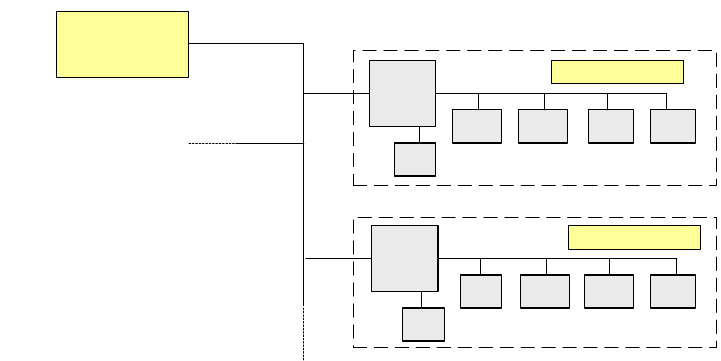
2.3.1.1 Basic structure
The 1-wire bus essentially consists of a master with an EEPROM (control unit) that controls vari-
ous sub-modules, such as the A/D converter, EEPROM, temperature and I/O modules. There is
a coupler connected upstream of each communication branch. This coupler opens the branch for
the exchange of data.
Fig. 2.3 - 1 Principle of the 1-wire bus
2
2
Slave
Master
Coupler
E²
A/D A/DA/D I/O
Coupler
E²
°C I/O°C
E²
Slave

Retrofit instructions: New 1-wire wiring for the SIPLACE X-series
11/2005 Edition
45
2.4 Parts required
2
2
2.4.1 Tools and consumables required
Set of hexagon socket spanners 2
Set of screwdrivers 2
Set of diagonal cutters 2
Cable ties 2
2
2
2
2
2
X4 retrofit package for the 1-wire bus, Cat 5
2 Wago terminal
2 Jumper for Wago terminal
2 24 V cable, 2-wire b/w
Item no.: 3009826-xx
2 24 V cable, 2-wire b/w
Item no.: 3009839-xx
2 5-pole Phoenix connector (female)
2 CAT 5 cable, 3m, to the 1-wire CAT5 distributor
Item no.: 3041626-xx
2 CAT 5 cable, 3m, to the 1-wire hub
Item no.: 3041627-xx
2 CAT 5 cable, 3m, to the 1-wire hub
Item no.: 3041628-xx
2 CAT 5 cable, 3m, to the 1-wire CAT5 gantry
Item no.: 3041629-xx
2 Board, 1-wire interface CAT5
Item no.: 03041578-02
4 Board, 1-wire CAT5 gantry
Item no.: 03042214-0102
2 1-wire CAT5 distributor
Item no.: 03040219-01
4 1-wire hub CAT5
Item no.: 03041473-02
2 1-wire jumper for cable between gantry boards
Item no.: 03042347-01
12 Self-adhesive cable clips
12 Cable ties
1 Retrofit Instructions
4 Retaining plate with modification 402012
8 Screws for the hubs on the retaining plate

Retrofit instructions: New 1-wire wiring for the SIPLACE X-series
11/2005 Edition
46
2.5 Safety instructions
WARNING
The safety instructions from the “Operational safety” chapter of the user manual and servicing in-
structions take precedence over these instructions. 2
The SIPLACE placement machines are supplied with mains voltage.
Consequently parts of these systems carry dangerous voltages! This voltage is present at certain
modules inside the machine base, even when the machine is switched off at the main power
switch.
Incorrect handling of the placement machine or touching live parts of the machine can result in
death or severe injury, and considerable damage to equipment.
BEFORE starting any work, shut down the operating system correctly, then switch the machine
OFF at the main power switch and disconnect from the main power supply. In addition, the com-
pressed air supply must be switched off at the compressed air unit's main valve in the machine
base and vented by actuating the needle valve on the compressed air unit.
There is DANGER for heart pacemaker wearers in the vicinity of the linear motors, as described
in detail in the "Special safety instructions for working in the vicinity of strong magnetic fields"
section of the user manual and service manual.
Always follow the accident prevention regulations, DIN or other standards and special safety
rules applicable in your country.
Pay attention to the information concerning residual voltages in the Operational Safety chapter.
Follow the ESD regulations as described in the operational safety section of the operating
instructions.
During the retrofit, always secure the machine to prevent access by other people and to prevent
it being switched on again. The procedure is described in the “Locking the machine…” section of
the user manual.
Working with the SITEST program further increases the risk of accident.
The SITEST program must only be used by authorized and trained personnel.
2
2.5.1 Definitions
2
CAUTION 2
2
2
2
PLEASE NOTE 2