00194705-0102_AI_1WireBus_DE+EN.pdf - 第73页
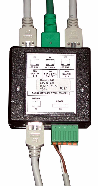
Retrofit instructions: New 1-wire wiring for the SIPLACE X-series 11/2005 Edition 73 2 Fig. 2.9 - 13 1-wire splitter; in th is case pulled out from the "sump"
Retrofit instructions: New 1-wire wiring for the SIPLACE X-series
11/2005 Edition
72
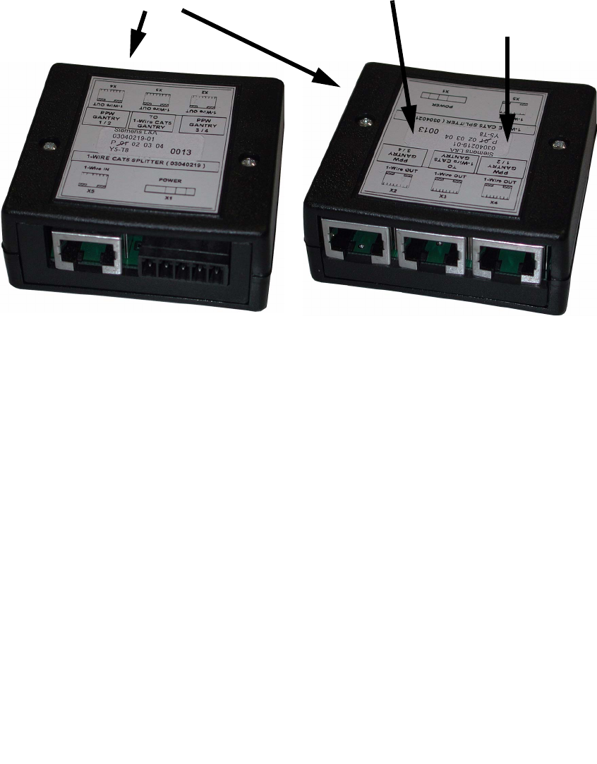
2.9.2.2 1-wire CAT5 splitter
2
Fig. 2.9 - 12 1-wire CAT5 splitter
2
: Fit two 1-wire CAT5 splitters in the machine - one per placement area.
: Place the 1-wire CAT5 splitter in the right-hand recess of the machine frame.
: Connect the CAT5 cable for the nozzle changers and temperature sensors and the 1-wire
bridge to the 1-wire CAT5 splitter (mat no.: 03040219-01) (see photograph on next page).
The splitter is also powered by a 24 V cable.
Individually: 2
PA1:
To X4 CAT5 cable for NC, gantry 1
To X3 CAT5 cable for temperature sensors, gantry 1 and 4
To X4 CAT5 cable for NC, gantry 4
To X1 24 V cable from sub-distributer
To X5 CAT5 cable from the 1-wire bridge on the sub-distributer
PA2:
To X4 CAT5 cable for NC, gantry 2
To X3 CAT5 cable for temperature sensors, gantry 2 and 3
To X4 CAT5 cable for NC, gantry 3
To X1 24 V cable from main distributor
To X5 CAT5 cable from the 1-wire bridge on the main distributor
1-wire CAT5 splitter
Connection for location 1/2
Connection for location 3/4
Retrofit instructions: New 1-wire wiring for the SIPLACE X-series
11/2005 Edition
73
2
Fig. 2.9 - 13 1-wire splitter; in this case pulled out from the "sump"
Retrofit instructions: New 1-wire wiring for the SIPLACE X-series
11/2005 Edition
74
2.9.2.3 1-wire hub CAT5
2
Fig. 2.9 - 14 1-wire hub CAT5
The 1-wire-hub CAT5 is needed for every location for the nozzle changer or/and component reject
bin sensor or nozzle reject bin sensor (see Fig. 2.9 - 14). 2
: Connect the CAT5 cable from the 1-wire CAT5 splitter.
: Connect the two round cables to the nozzle changers, row 1 and row 2.
: Label each connection (NC1 and NC2) on the side of the box.
: Plug in the connector for the sensors at X2:
The connector for the sensors is connected at X2.
Sensor S1 for component and sensor S2 for nozzle.
: Screw the 1-wire-hub CAT5 to the plate fitting (the plate fitting is only present on X docking unit
frames).
Relieve the strain on the round cables using cable ties, as shown in Fig. 2.9 - 16.
2
2
2
2
2