00194705-0102_AI_1WireBus_DE+EN.pdf - 第60页
Retrofit instructions: New 1-wire wiring for the SIPLACE X-series 11/2005 Edition 60 : Wire up the components as shown in the drawing. Cable and hose carrier interface P4 Cable and hose carrier interface P1 Cross-beam NC…
Retrofit instructions: New 1-wire wiring for the SIPLACE X-series
11/2005 Edition
59
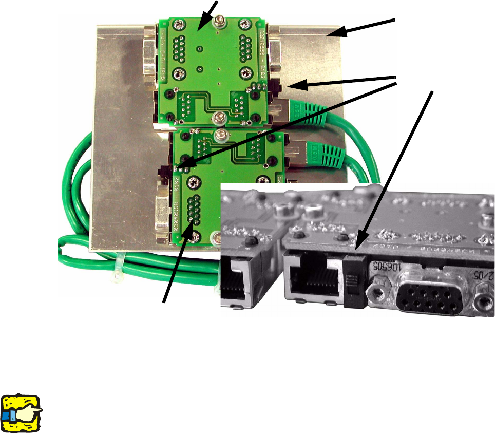
: Check that the switches on both sides of the 1-Wire CAT 5 temp are in the top position (the
position on the PCB), and move them up if necessary.
2
2
2
2
The 1-wire CAT5 gantry module will later be connected directly to the CAN bus module of the ca-
ble and hose carrier interface as a small board (see variant 2). 2
2
Switch
1-wire CAT5 temp
Locations 4/3
Locations 1/2
Processing area 1: 4 + 1
Processing area 2: 3 + 2
Retrofit instructions: New 1-wire wiring for the SIPLACE X-series
11/2005 Edition
60
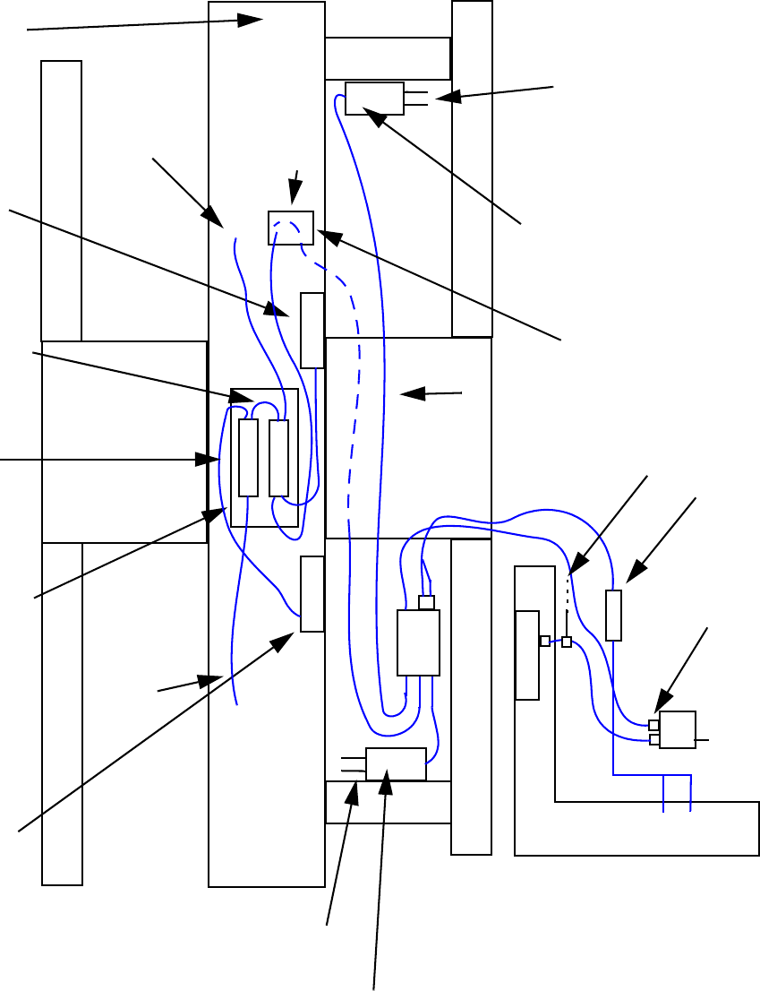
: Wire up the components as shown in the drawing.
Cable and hose carrier interface P4
Cable and hose carrier interface P1
Cross-beam
NC
NC
PCB: 1-wire CAT5 temp
Pneumatic unit
1-wire HUB, nozzle changer
NC (nozzle changer)
connection, row 1/2
NC (nozzle changer)
connection, row 1/2
PCB direction of travel
4
1
CAN bus cable
from the machine
CAN bus cable
from the machine
Pin 1
Pin 2
0V
24V
CAT5 cable
connection
Plug-in connector
Sub/main
distributor
1 NC connection for location 3 or 4
2 NC connection for location 1 or 2
3 Connection to the 1-wire CAT5 temp board
1-wire hub NC
CAT5 cable
1
2
3
Opening in the cross-beam
for running the cables
On the back panel there are PCBs for gantry 3/2
RS232
P4
P1
To the machine CAN bus cable
Retrofit instructions: New 1-wire wiring for the SIPLACE X-series
11/2005 Edition
61
: Check the temperature sensors and the nozzle changers.
: Calibrate the nozzle changers.
: Secure all loose cables with cable ties.
: Fit all the covers.
2
2
2
2
2
2
2
2
2
2
2
2
2
2
2
2
2
2
2
2
2
2
2
2
2