00194705-0102_AI_1WireBus_DE+EN.pdf - 第5页
Nachrüstanleitung Neue 1-Wire-Verkabelung SIPLACE X-Serie Ausgabe 11/2005 5 1 Nachrüst anleitung Neue 1-Wire-V erkabelung SIPLACE X-Serie 1.1 V orteile der neuen V e rkabelung – Die neue V erkabelung des 1-Wire-Bus elimi…
Nachrüstanleitung / Retrofit instructions Neue 1-Wire Verkabelung / New 1-wire wiring SIPLACE X-series
Ausgabe 11/2005 Edition
4
2 Retrofit instructions:
New 1-wire wiring for the SIPLACE X-series . . . . . . . . . . . . . . . . . . . . . . . . . . . . . . 43
2.1 Advantages of the new wiring . . . . . . . . . . . . . . . . . . . . . . . . . . . . . . . . . . . . . . . . . . . . . . . . . . . . 43
2.2 Variants of the new wiring. . . . . . . . . . . . . . . . . . . . . . . . . . . . . . . . . . . . . . . . . . . . . . . . . . . . . . . . 43
2.3 One-wire bus . . . . . . . . . . . . . . . . . . . . . . . . . . . . . . . . . . . . . . . . . . . . . . . . . . . . . . . . . . . . . . . . . . 43
2.3.1 Structure of the 1-wire bus. . . . . . . . . . . . . . . . . . . . . . . . . . . . . . . . . . . . . . . . . . . . . 44
2.3.1.1 Basic structure . . . . . . . . . . . . . . . . . . . . . . . . . . . . . . . . . . . . . . . . . . . . . . . . . . . . 44
2.4 Parts required. . . . . . . . . . . . . . . . . . . . . . . . . . . . . . . . . . . . . . . . . . . . . . . . . . . . . . . . . . . . . . . . . . 45
2.4.1 Tools and consumables required. . . . . . . . . . . . . . . . . . . . . . . . . . . . . . . . . . . . . . . . 45
2.5 Safety instructions. . . . . . . . . . . . . . . . . . . . . . . . . . . . . . . . . . . . . . . . . . . . . . . . . . . . . . . . . . . . . . 46
2.5.1 Definitions . . . . . . . . . . . . . . . . . . . . . . . . . . . . . . . . . . . . . . . . . . . . . . . . . . . . . . . . . 46
2.6 Preparatory work . . . . . . . . . . . . . . . . . . . . . . . . . . . . . . . . . . . . . . . . . . . . . . . . . . . . . . . . . . . . . . . 47
2.7 New 24 V wiring . . . . . . . . . . . . . . . . . . . . . . . . . . . . . . . . . . . . . . . . . . . . . . . . . . . . . . . . . . . . . . . . 48
2.8 Variant 1 . . . . . . . . . . . . . . . . . . . . . . . . . . . . . . . . . . . . . . . . . . . . . . . . . . . . . . . . . . . . . . . . . . . . . . 52
2.8.1 CAN bus cable at RS232 bridge . . . . . . . . . . . . . . . . . . . . . . . . . . . . . . . . . . . . . . . . 52
2.8.2 Fitting the 1-wire-hub . . . . . . . . . . . . . . . . . . . . . . . . . . . . . . . . . . . . . . . . . . . . . . . . . 54
2.8.3 Replacing the nozzle changer control board for the C&P 20. . . . . . . . . . . . . . . . . . . 56
2.8.4 PCB, 1-wire CAT5 gantry . . . . . . . . . . . . . . . . . . . . . . . . . . . . . . . . . . . . . . . . . . . . . 57
2.8.5 Cable and hose carrier interface . . . . . . . . . . . . . . . . . . . . . . . . . . . . . . . . . . . . . . . . 58
2.9 Variant 2 . . . . . . . . . . . . . . . . . . . . . . . . . . . . . . . . . . . . . . . . . . . . . . . . . . . . . . . . . . . . . . . . . . . . . . 65
2.9.1 1-wire bus in the SIPLACE X. . . . . . . . . . . . . . . . . . . . . . . . . . . . . . . . . . . . . . . . . . . 65
2.9.2 Fitting the new variant . . . . . . . . . . . . . . . . . . . . . . . . . . . . . . . . . . . . . . . . . . . . . . . . 71
2.9.2.1 1-wire bridge . . . . . . . . . . . . . . . . . . . . . . . . . . . . . . . . . . . . . . . . . . . . . . . . . . . . . . 71
2.9.2.2 1-wire CAT5 splitter . . . . . . . . . . . . . . . . . . . . . . . . . . . . . . . . . . . . . . . . . . . . . . . . 72
2.9.2.3 1-wire hub CAT5. . . . . . . . . . . . . . . . . . . . . . . . . . . . . . . . . . . . . . . . . . . . . . . . . . . 74
2.9.2.4 1-wire CAT5 gantry. . . . . . . . . . . . . . . . . . . . . . . . . . . . . . . . . . . . . . . . . . . . . . . . . 77
2.9.2.5 1-wire CAT5 TEMP new (essential for the IGUS cable and hose carrier) . . . . . . . 79
2.9.3 Final tasks . . . . . . . . . . . . . . . . . . . . . . . . . . . . . . . . . . . . . . . . . . . . . . . . . . . . . . . . . 79
Nachrüstanleitung Neue 1-Wire-Verkabelung SIPLACE X-Serie
Ausgabe 11/2005
5
1 Nachrüstanleitung
Neue 1-Wire-Verkabelung SIPLACE
X-Serie
1.1 Vorteile der neuen Verkabelung
– Die neue Verkabelung des 1-Wire-Bus eliminiert interne Kommunikationsprobleme.
– Das Kabel für den 1-Wire-Bus wird im Bereich der Stellplätze aus dem Maschinen-CAN-Bus-
Kabel entfernt und über speziell abgeschirmte Kabel geführt.
– Weiter wird die Qualität der 24V-Versorgung durch einen Spannungsregler auf der Steuerpla-
tine im Pipettenwechsler verbessert.
1.2 Varianten der neuen Verkabelung
Es gibt zwei Varianten der neuen Verkabelung. Falls ein Teil der älteren Variante, von der es ca.
30 Maschinen im Feld gibt, ausfällt und getauscht werden muß, muß die ganze Verkabelung auf
die neue Variante umgebaut werden. 1
Die 24 V - Versorgung muß bei beiden Varianten eingebaut werden. 1
1.3 One Wire Bus
Mit Einführung des Message-loop in der SW 505 (601) wurde es notwendig die Anzahl der Ein-
und Ausgänge zu reduzieren oder ein zusätzliches E/A Modul zu installieren. Aufgrund der Platz-
situation in der Maschine und Kostengründen, wurde das "One Wire Bus - System eingeführt.
Der One Wire Bus steuert den Pipettenwechsler in allen 4 Sektoren, überträgt die Temperatur-
werte der Sensoren an den Kopfplatten und liest die Portaldaten aus.
Nachrüstanleitung Neue 1-Wire-Verkabelung SIPLACE X-Serie
Ausgabe 11/2005
6
Aufgaben
(1) Steuerung Pipettenwechsler 6/12 C&P Köpfe (1.und 2. Reihe)
(2) Steuerung Pipettenwechsler 20 C&P Köpfe (1.und 2. Reihe), mit Magazinabfrage
(3) 2 Temperatursensoren je Portal an der Kopfplatte befestigt.
(4) Speicherung der Portalidentifizierung auf einem EEPROM
(Es wird zwischen Platten-Portal CFK 02, DTC- Portal CFK 04 und dem Portal CFK 06 unter-
schieden. Daraus folgt, das je nach Portaltyp eine andere Maschinendatenbank für die Dyna-
mikparameter der Hauptachsen geladen wird).
(5) Option:Abfrage der Abwurfbehälter in allen 4 Sektoren
1.3.1 Aufbau One Wire Bus
Wie der Name schon sagt werden die Daten über eine Ader übertragen. Die Daten werden also
seriell an das Subsystem gesendet.
Der One Wire Bus wird bei zeitunkritischem Abläufen eingesetzt und lässt sich als single Master
Bus mit „beliebig“ vielen Slaves (Teilnehmern) realisieren.
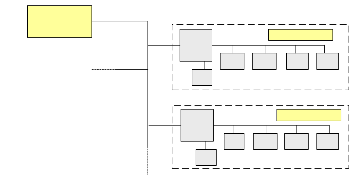
1.3.1.1 Prinzipieller Aufbau
Der One Wire Bus besteht grundsätzlich aus einem Master mit einem EEPROM (Steuereinheit),
der die verschiedenen Submodule wie A/D-Wandler, EEPROM,Temperatur und I/O-Bausteinen
ansteuert. Jedem Kommunkationszweig ist ein Coupler vorgeschaltet, der den Zweig zum Daten-
austausch öffnet.
Abb. 1.3 - 1 Prinzip One Wire Bus
1
1
Slave
Master
Coupler
E²
A/D A/DA/D I/O
Coupler
E²
°C I/O°C
E²
Slave