00194705-0102_AI_1WireBus_DE+EN.pdf - 第74页
Retrofit instructions: New 1-wire wiring for the SIPLACE X-series 11/2005 Edition 74 2.9.2.3 1-wire hub CA T5 2 Fig. 2.9 - 14 1-wire hub CA T5 The 1-wire-hub CA T5 is needed for every loca tion for the nozzle changer or/…
Retrofit instructions: New 1-wire wiring for the SIPLACE X-series
11/2005 Edition
73
2
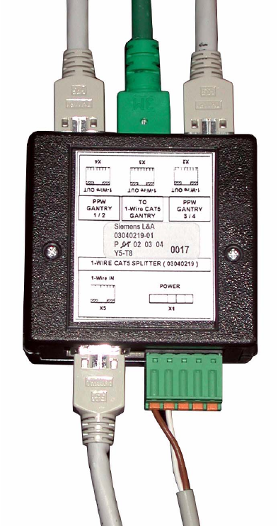
Fig. 2.9 - 13 1-wire splitter; in this case pulled out from the "sump"
Retrofit instructions: New 1-wire wiring for the SIPLACE X-series
11/2005 Edition
74
2.9.2.3 1-wire hub CAT5
2
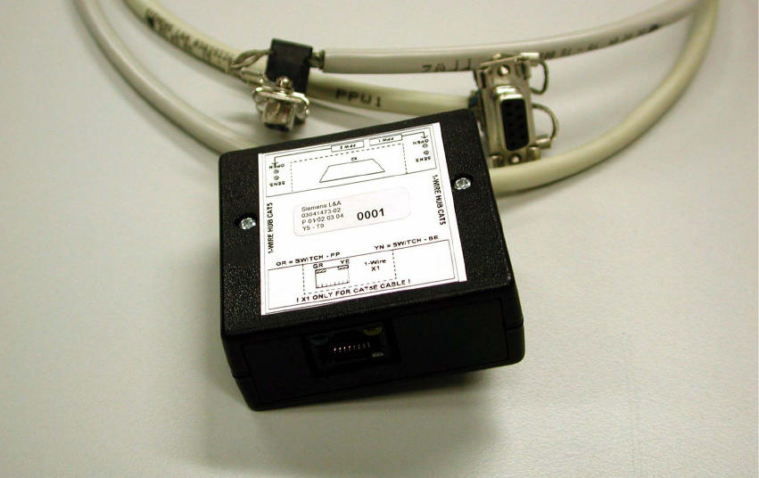
Fig. 2.9 - 14 1-wire hub CAT5
The 1-wire-hub CAT5 is needed for every location for the nozzle changer or/and component reject
bin sensor or nozzle reject bin sensor (see Fig. 2.9 - 14). 2
: Connect the CAT5 cable from the 1-wire CAT5 splitter.
: Connect the two round cables to the nozzle changers, row 1 and row 2.
: Label each connection (NC1 and NC2) on the side of the box.
: Plug in the connector for the sensors at X2:
The connector for the sensors is connected at X2.
Sensor S1 for component and sensor S2 for nozzle.
: Screw the 1-wire-hub CAT5 to the plate fitting (the plate fitting is only present on X docking unit
frames).
Relieve the strain on the round cables using cable ties, as shown in Fig. 2.9 - 16.
2
2
2
2
2
Retrofit instructions: New 1-wire wiring for the SIPLACE X-series
11/2005 Edition
75
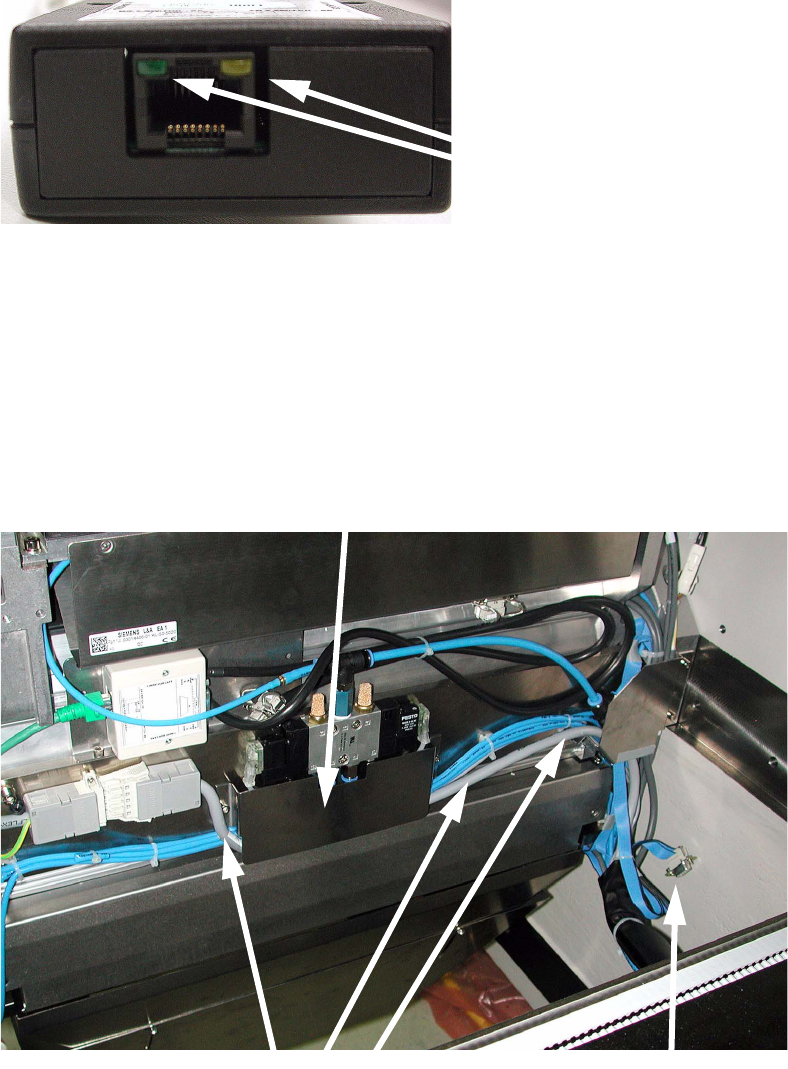
There are two LEDs at connection X1:
The yellow LED indicates whether a component reject bin is in use.
The green LED indicates whether a nozzle reject bin is in use. 2
2
Fig. 2.9 - 15 LED for component and reject bin sensor
: Run the power cable for the FCU (item no.: 03020610-01) beneath the "guide plate" (see pho-
tograph below).
With the docking unit with TwinHead configuration it is not necessary to run the cable since the
nozzle changer for the TwinHead is not controlled via the 1-wire bus.
: Fold up the CAN cable and tie it to the cable (item no.: 0301957-01) using cable ties.
2
LEDs
Metal cover
Now unused
machine-CAN bus cable
FCU cable