00194705-0102_AI_1WireBus_DE+EN.pdf - 第65页
Retrofit instructions: New 1-wire wiring for the SIPLACE X-series 11/2005 Edition 65 2.9 V ariant 2 2.9.1 1-wire bus in the SIPLACE X On the SIPLACE X machine, the 1-wire bus runs vi a a separate CA T5 cable from the sub…
Retrofit instructions: New 1-wire wiring for the SIPLACE X-series
11/2005 Edition
64
2
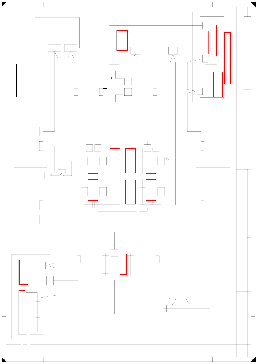
Fig. 2.8 - 3 X4 circuit diagram
X30_1sq
So
X30_2tq
So
X30_1tq
X146
CAN OUT
Pin
4
1-wire CAT5 interface
0304 1578 (qf)
X2qf
X2rf
CAN I/O module 00355 051 (rb)
So
0304 1578
1-wire CAT5 interface (rf)
X2rf
Axis unit 1/4
0301 6110
CAN
0301 6643
X7pn X6pn
X7pn
So
CAN card
X6pn
CAN bus 1CAN bus 2
So
X30_2tq X30_1tq
CAN
0301 0052
0301 0059
Distributor
0304 0219 (qk)
X5qk
X5qk
X3qk
X3qk
X6qf
X6qf
0304 1626
Patch cable 3 m
X5rk
X5rk
Distributor
0304 0219
0304 1626
Patch cable 3 m
X6rf
X6rf
0301 0053
X1hq
X4qk
X2qk
X2qk
To 1-wire hub CAT5
X1gq
X4qk
To 1-wire hub CAT5
0304 1627
Patch cable 3 m
0304 1628
Patch cable 3 m
X1qk
X1qk
0300 9826
X2rk
X1fq
X4rk
X1kq
X2rk
To 1-wire hub CAT5
To 1-wire hub CAT5
0304 1627
Patch cable 3 m
0304 1628
Patch cable 3 m
X15qa
X15qa
X15ra
X15ra
X1rk
X1rk
0300 9839
X3rk
X3rk
X4rk
A
B
C
D
E
F
A
B
C
D
E
F
Designer 9
14.11.2001
Tekin
SIPLACE X4 basic module
7
Tek
Tek
Tek
Vision control
00363961 (qd)
CAN
Main distributor 0301 0004 (qa)
X2qd
X2qd
CAN
X2qf
Dock.unit 2 Dock.unit 1
X125X126
CAN INCAN OUT
21 786543
21 786543
X115X116
CAN INCAN OUT
CAN
PCB control
X22ao
X22ao
CAN I/O module 00355 051 (qb)
So
PinSoPin
So
So
0301 0050
0301 0051
X2rd
X145
CAN IN
So
So
Axis unit 2/3
0301 6110
X30_2sq
CAN
Dock.unit 3
X136
CAN OUT
Pin
X2rd
CAN
CAN
Sub-distributor 0301 0005 (ra)
Vision control
00363961 (rd)
Dock.unit 4
0301 0054
Computer unit
X135
CAN IN
So
So
X68
Ambient pressure sensor
Pneumatic unit
Placement area 2
Placement area 1
CAN bus wire assignment
Wire no. assignment, Sub-D PIN
1
2
3
4
5
6
7
8
9
CAN
X30_2sq
X30_1sq
So
Weitergabe sowie Vervielfältigung dieser Unterlage, Verwertung und
Mitteilung ihres Inhalts nicht gestattet, soweit nicht ausdrücklich zugestanden.
Zuwiderhandlungen verpflichten zu Schadenersatz. Alle Rechte vorbehalten,
insbesondere für den Fall der Patenterteilung oder GM-Eintragung.
Comunicado como segredo empresarial. Reservados todos os direitos.
Confiado como secrete industrial. Nos reservamos todos los derechos.
Confie a titre de secret d'entreprise. Tous droits reserves.
Proprietary data, company confidential. All rights reserved.
Status Modified Date Name Stand.
Check.
Author
Date
Orig. Repl. f. Repl. by
Item name
SIPLACE X series
Document number:
Sheet
Sh.
GND
CAN_INT
PowerFail
Spare
RESET
"1-Wire"
CAN_H
CAN_L
GND
3
9
5
8
4
2
7
6
1
1-wire CAT5
1-wire CAT5
(rk)
CAN In
CAN In
So
Switch pos.: bottom
0304 2214 (ge)
1-wire CAT5 gantry
Cable carrier interface
Switch pos.: top
0304 2214 (he)
1-wire CAT5 gantry
So
Cable carrier interface
Patch cable 3 m
0304 1629
G3
X1ge
X1he
X40ca
X5he
X2he
X2he
X40ca
X4he
CAN
0304 2347
0301 0622
0301 0612
1-wire bridge
P2
X2ge
X2ge
X40ba
CAN
X4ge
X1ge
X40ba
X5ge
G4
X5ke
1-wire CAT5 gantry
X40da
X4ke
X40da
Switch pos.: top
0304 2214 (ke)
CAN
So
CAN In
Spare
X30_1sq
X1ke
X2ke
X2ke
0304 2214 (fe)
X4fe
Switch pos.: bottom
Cable carrier interface
Cable carrier interface
X40aa
CAN
(ca)
(ba)
0301 0622
0301 0612
P1
(da)
(aa)
1-wire bridge
0304 2347
X2fe
X2fe
X5fe
1-wire CAT5 gantry
X40aa
CAN In
So
X1fe
X1fe
Patch cable 3 m
0304 1629
RS05
RS04
RS03
402006
401892
401582
30.09.05
27.07.05
15.06.05
90010131-010501LD3
See page 3-20
See page 5-35
See page 3-13
See page 5-35
See page 4-16
See page 5-55
See page 5-55
See page 5-56
See page 4-16
See page 5-56
See page 5-70
See page 3-9
See page 5-72
See page 5-70
See page 5-27
See page 5-72
See page 5-73 See page 5-73
See page 5-73 See page 5-73
Retrofit instructions: New 1-wire wiring for the SIPLACE X-series
11/2005 Edition
65
2.9 Variant 2
2.9.1 1-wire bus in the SIPLACE X
On the SIPLACE X machine, the 1-wire bus runs via a separate CAT5 cable from the sub or main
distributor to the cable and hose carrier interface. From the cable and hose carrier interface to the
head interface, the 1-wire bus runs in the cable and hose carrier. This means that the structure of
the cable run has changed, but the function remains the same.
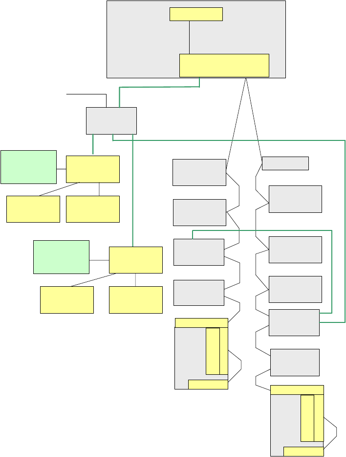
Fig. 2.9 - 1 Overview of the one-wire stations with reference to PA1 on the SIPLACE X
Vision control
unit,
sector 4
Conveyor
control unit
A x is u n it
PA 1
COM Board
I/O SUB m odule,
sector 4
One-wire bridge
(d riv e r)
Nozzle changer
hub (coupler),
gantry 4
C O table 4,
ta p e c u tte r
Conrol board
N C (C & P 2 0 ),
ro w 1
Control board
N C (C & P 2 0 ),
ro w 2
Trailing interface,
gantry 4
C O table 1,
ta p e c u tte r
Trailing interface,
gantry 1
Tem p.sensor
Head
plate
Tem p.sensor
O ption: C heck reject bin
or term inating plug
Attention: no C AN -
term inating resistor
TQM Module
(M a s te r)
RS232
Machine CAN bus
1-wire CAT5,
gantry 4
Head interface
1-wire CAT5,
gantry 4
Tem p.sensor
Head
plate
Tem p.sensor
G antry
recognition
Head interface
1-wire CAT5
distributor
24V for the nozzle changer
1-wire CAT5 cable
1-wire CAT5 cable
1-wire CAT5 cable
1-wire CAT5 cable
1-wire CAT5 cable
Nozzle changer
hub (coupler),
gantry 1
NC control board
(C &P20),
ro w 2
NC conrol board
(C & P 2 0 ),
ro w 1
O ption: C heck reject bin
or term inating plug
Attention: no CAN-
te rm in a tin g re s is to r
Gantry
recognition

Retrofit instructions: New 1-wire wiring for the SIPLACE X-series
11/2005 Edition
66
The design of the 1-wire bus is exactly the same in PA2, depending on the machine configuration
(1 or 2 gantries).
Description of the functions: 2
Each 1-wire bus is assigned a fixed CAN ID when the machine is switched on.
1-wire in PA1 --> CAN ID: 07d0
1-wire in PA2 --> CAN ID:07c0
While the bus system is initializing, each station logs onto the master and the bus switches to
standby.
At rest, the voltage level on the 1-wire bus is 5V.
The bus can be initialized again using the CACCIA tool (see Checking the functions and trouble-
shooting during servicing).
Connector assignment: machines/CAN bus:
Fig. 2.9 - 2 Pin assignment: sub D connector
Components of the 1-wire bus 2
Modules:
(1) 1-wire RS232 bridge on the SUB/MAIN module (subsequently integrated into the I/O module)
(2) 1-wire CAT5 gantry on the cable and hose carrier interface (board between CAN bus and
cable and hose carrier interface)
(3) 1-wire CAT5 distributor
(4) 1-wire hub nozzle changer
(5) Nozzle changer control board (integrated into the NC, not for DLM heads)
(6) 1 set of temperature sensors (must all be replaced at the same time since they are dependent
on the serial number)
(7) Gantry identification (EEPROM)
120
Ohm
CAN Interrupt95
+24V 1-wire-Bus89
Power Fail74
CAN Reset68
GND53
CAN High47
CAN Low32
GND26
1-wire-Bus 11
AderPin
PIN 1 on HF machines only