00194313-03.pdf - 第57页
SIPLACE S-25 HM / S-27 HM 2 Assembly Inst ructions for PCB Camera, Multicolor 02/2007 Edition 2.5 Preparatory Steps 57 2.5 Prep aratory Step s : Open the safety hoods. : Remove the reject bin. : Disassemble the cover of …

2 Assembly Instructions for PCB Camera, Multicolor SIPLACE S-25 HM / S-27 HM
2.4 Assembly Kits, Tools 02/2007 Edition
56
2.4 Assembly Kits, Tools
2.4.1 Assembly Kit "PCB Camera Multicolor S-25 HM / S-27 HM"
2
2.4.2 Tools, Auxiliary Test Equipment and Expendable Materials
– Drill, possibly cable drum
(only for S.25 HM with a manufacturing date Sep to Dec 98)
– Drill bits for core diameter 3.3 mm and thread cutter M4
(only for S.25 HM, with a manufacturing date Sep to Dec 98)
– Vacuum cleaner (only for S.25 HM, with a manufacturing date Sep to Dec 98)
– Set of Allen wrenches
– Oblique-nosed cutting pliers
– Open-end wrench or size 6 mm socket wrench (only for HS-50)
– Wire stripper
– ESD bracelet
– Crimping pliers made by AMP (for connector sleeves)
– Insulating tape and permanent marker
– Ethyl alcohol.
1 Assembly Kit "PCB Camera Multicolor S-25 HM / S-27 HM" Item no. 00358042-01
2
PCB Camera Multicolor assembly, made by Sticksel LP-Kamera
Multicolor, Fa. Sticksel each with 2 connection cables
Item no. 00355462-01
2
Spacer plate (= adapter) Item no. 00348078-01
6
hex head cap screw M3 x 14 (captive) Item no. 00327105-01
2
PCB camera board, modular, made by Sticksel Item no. 00344490-01
1
Assembly kit 50 V module for PCB camera S-25 HM / S-27 HM,
consisting of:
Item no. 00357863-01
1 Relay RS 30 / 24 VDC GSE 1 A,
manufacturer: Weidmüller: Order no. 11 01 66
Item no. 00345646-01
1 Converter 24V/50V 50 mA, Siemens AG (universal illumination
converter)
Item no. 00349095-01
1 Retrofit cable for voltage module, 50 V, consisting of: Item no. 00356979-01
Cable W1 with 2 connector sleeves and 1 twin connector sleeve
Cable W2, complete, with 1 connector sleeve *)
Cable W3, complete, with 1 connector sleeve *)
Cable W4, complete, with connector sleeves
Cable W 5, complete, with 2 connector sleeves
7 Twin connector sleeves 2 x 1.5 mm
2
, Order no. 18H 7081,
Bürklin (1unit = reserve)
Order no. 18H 7081
SIPLACE S-25 HM / S-27 HM 2 Assembly Instructions for PCB Camera, Multicolor
02/2007 Edition 2.5 Preparatory Steps
57
2.5 Preparatory Steps
: Open the safety hoods.
: Remove the reject bin.
: Disassemble the cover of the feeder modules.
: Undock the movable component changeover tables
: Turn the machine OFF at the main switch, isolate the machine from the mains, turn OFF the
flow of compressed air at the compressed air uni
: Push the X-gantries toward the outside of the machine so that the placement heads are readily
accessible.
2.5.1 Assembly in the Terminal Panel, Right Side
NOTE:
Ascertain you before starting assembly, what kind of clamping field is in the machine
see chapters 2.5.1, 2.5.3 and 2.5.4. 2
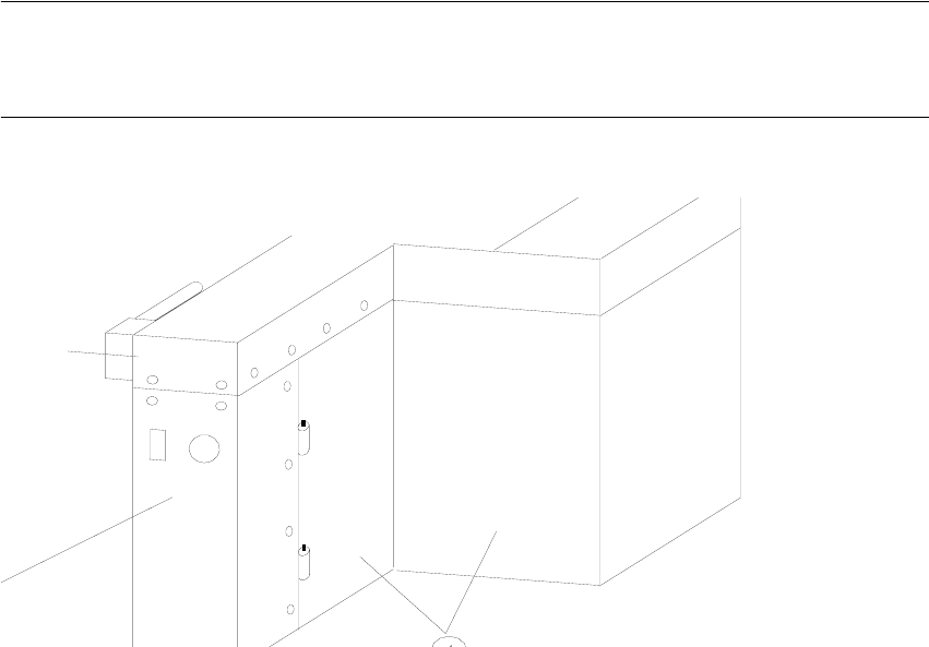
Abb. 2.5.1 Opening the Machine Frame Doors (Service Cabinets for Terminal Panel, Right Side)
Key:
1. Machine frame doors
2. Lateral protection (remains installed)
2 Assembly Instructions for PCB Camera, Multicolor SIPLACE S-25 HM / S-27 HM
2.5 Preparatory Steps 02/2007 Edition
58
: Open the machine frame doors on the terminal panel, right side.
: Loosen the screw fastening the servo unit (loosen the M5 socket hex head screw) and lift the
servo unit out.
2
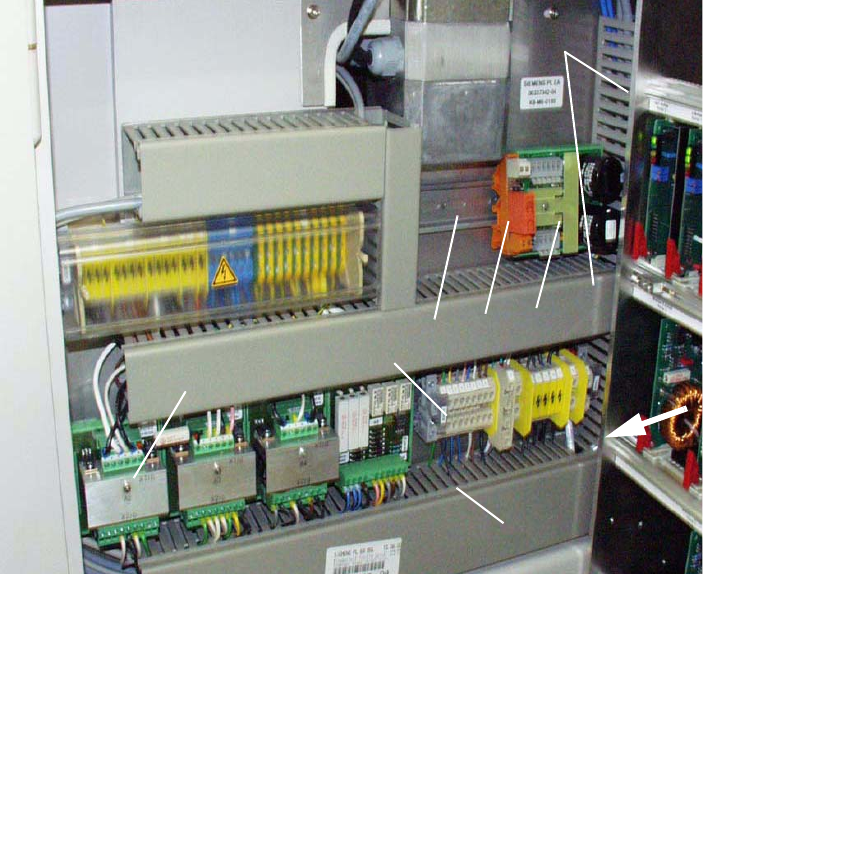
Abb. 2.5.2 Terminal Panel, RH Side: X207; Location for Install. Voltage Module 50 V + Relay K1
2
2
2
2
2
2
1 Servo-unit (remove)
2 Cable pits: remove cover
3 Top hat rail (install, if necessary)
Fasteners: 2 washers A4.2 and 2 socket hex head cap screws M4
4 50 V voltage regulator module 50 S-25 HM / F5 HM
5 Relay K1 S-25 HM / F5 HM
6 Terminal strip X207
7 Rectifier module A2
1
2
4
5
3
6
2
7