00194313-03.pdf - 第73页
SIPLACE S-25 HM / S-27 HM 2 Assembly Inst ructions for PCB Camera, Multicolor 02/2007 Edition 2.2 Installing PCB Camera Board and PCB Camera Multicolor 73 2.2.3 Inst alling the "PCB Camera Bo ard, Modular" from…
2 Assembly Instructions for PCB Camera, Multicolor SIPLACE S-25 HM / S-27 HM
2.2 Installing PCB Camera Board and PCB Camera Multicolor 02/2007 Edition
72
Following the configuration of the Multicolor PCB camera at the line computer, including descri-
bing the PCB or substrate (entry of the thickness), a message can be accessed at the line com-
puter as a check (see Abschn. 2.3.1). 2
In most cases, adequate imaging quality will still be achieved even it work is done outside the ran-
ges indicated above.
With the spacer plate removed, system fiducials can still be adequately recognized. 2
: Ascertain the PCB/substrate thickness to be processed now.
: Use the table to determine whether the distance plate is required.
If YES, place the distance plate (see Abb. 2.7.4 -> 1) from the camera assembly kit on the ca-
mera’s assembly surface in the correct rotational position (this is determined on the basis of
the holes).
2
: Place the PCB camera Multicolor, including the distance plate, if applicable, in the correct po-
sition on the distance bolts (HS-50) or directly on the camera holder from below (S-25 HM).
: Use the 3 captive hex head cap screws M 3 x 14 to screw the camera to the camera holder.
: Fasten the cables with the two cable ties.
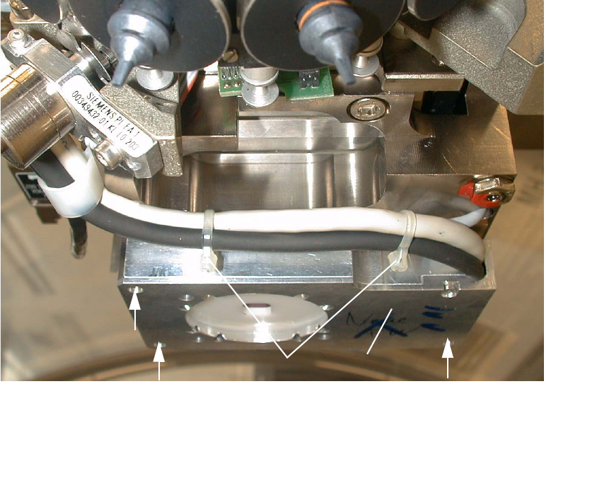
Abb. 2.2.5 Fastening the PCB Camera Multicolor (View from below, diagonally)
1 PCB camera Multicolor
2 Fasteners: 3 hex head cap screws M3 x 14 (captive)
3 2 Cable ties
2
2
21
3
SIPLACE S-25 HM / S-27 HM 2 Assembly Instructions for PCB Camera, Multicolor
02/2007 Edition 2.2 Installing PCB Camera Board and PCB Camera Multicolor
73
2.2.3 Installing the "PCB Camera Board, Modular" from the Assembly Kit
: Check the serial number of the PCB camera board, modular: It must correspond to the number
on the Multicolor PCB camera. Per gantry this allocation must be maintained during installa-
tion. The position of the number is shown in the following illustration.
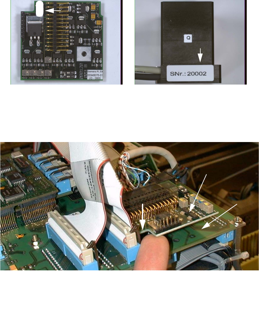
Abb. 2.2.6 Check: Identical Serial Number on Modular PCB Camera Board and PCB Camera Multicolor
: Screw the distance holders of the assembly kit on the "vision board modular".
: Plug the "PCB camera board, modular" onto the "Vision board, modular" in the correct position,
as shown above.
2
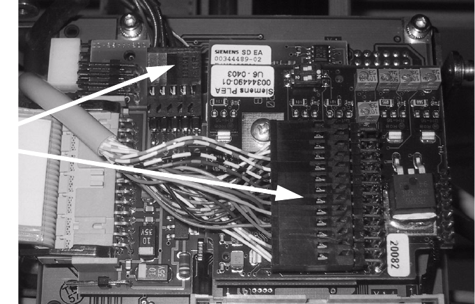
Abb. 2.2.7 Installing the "PCB Camera Board, Modular" from Assembly Kit (Using HS-50 as an Example)
: Fix the PCB board modular.
1 Head PCB HS-50 assembly (modular)
2 PCB camera board, modular, manufacturer = Sticksel
3 Position of the recess
20002
3
2
1
2 Assembly Instructions for PCB Camera, Multicolor SIPLACE S-25 HM / S-27 HM
2.2 Installing PCB Camera Board and PCB Camera Multicolor 02/2007 Edition
74
2.2.4 Laying Cables, Plugging into PCB Camera Board and Vision Board
: Run the two cables from the PCB camera Multicolor up to the head PCBs.
: Plug the connectors of the PCB camera Multicolor into the "Vision board modular" and into the
"PCB camera, modular" located above it.
2
: Fasten the cables running upward such that the strain on the connectors is relieved.
: Plug the ribbon cables.
2.2.5 Assembling the Placement Head and the Machine
: Place the covers previously removed back on the placement heads. Fasten the covers with 5
screws each.
: Place the covers on to cable pits.
: Re-install the servo unit (socket hex head cap screw M5).
: Apply screw-locking compound to the screw.
: Remove all of the tools, etc., from the machine’s working area.
: Mount the feeder covers.
: Turn the machine on at the main switch. The compressed air must be connected.
: Dock all movable component changeover tables with the previous allocation.
: Close the safety doors and safety hoods.
Connect
camera cables