00194313-03.pdf - 第69页
SIPLACE S-25 HM / S-27 HM 2 Assembly Inst ructions for PCB Camera, Multicolor 02/2007 Edition 2.2 Installing PCB Camera Board and PCB Camera Multicolor 69 2.2.1 Removing PCB Camera (Normal Illu mination) incl. Ob lique I…
2 Assembly Instructions for PCB Camera, Multicolor SIPLACE S-25 HM / S-27 HM
2.2 Installing PCB Camera Board and PCB Camera Multicolor 02/2007 Edition
68
2.2 Installing PCB Camera Board and PCB Camera
Multicolor
At S-25 HM possibly the modular head PCB assembly is not installed yet. 2
2
Abb. 2.2.1 Conversion PCB "small axis" still installed (= old PCB version)
: If the conversion PCB "small axis" is still installed on the placement head, assembly the mo-
dular head PCB unit now on the basis of its own assembly instructions (see chapter "Require-
ments").
At S-27 HM the modular head PCB assembly is always installed. 2
CAUTION
Comply the ESD regulations during the following handling of the PCBs.
Make certain that no screws or other parts drop into the machine or the placement head !! 2
SIPLACE S-25 HM / S-27 HM 2 Assembly Instructions for PCB Camera, Multicolor
02/2007 Edition 2.2 Installing PCB Camera Board and PCB Camera Multicolor
69
2.2.1 Removing PCB Camera (Normal Illumination) incl. Oblique Illumination
Execute the following steps at each gantry.
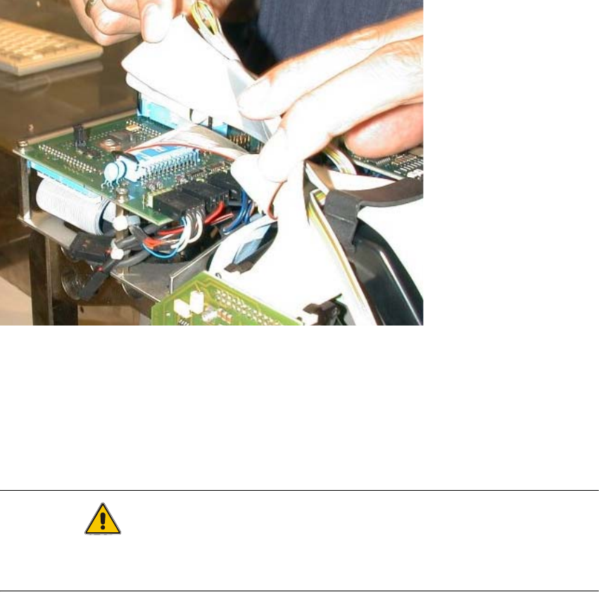
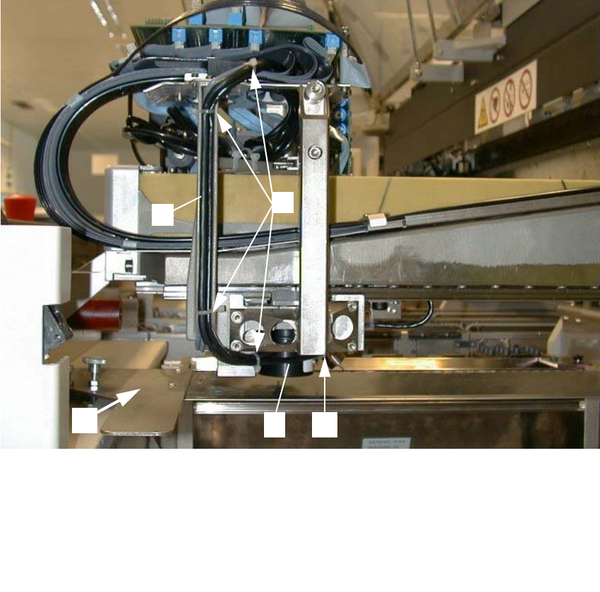
Abb. 2.2.2 Loosening Cable Ties, Removing Subgantry PCB Camera (Using HS-50 as an Example)
*) Cable routing for S-25 HM: see Abb. 2.6.9.
: Remove the cover over the placement heads (undo 5 screws on each).
: Undo the flat cables above the placement head.
: Undo the cable ties along the cable harness.
: In case of initial situation "old PCB camera with head PCB moduar": On the "Vision board, mo-
dular" unplug the connectors of the subgantry PCB camera (normal illumination) and - if pre-
sent - the oblique illumination.
1 Cover of feeder modules: to be removed
2 U-shaped rail for cable guide *)
3 4 unit, cable ties
4 Subgantry PCB camera (with normal illumination) to be removed)
5 Fasteners for the PCB camera: 3 socket hex head cap screws M3 x 10
2
3
45
1
2 Assembly Instructions for PCB Camera, Multicolor SIPLACE S-25 HM / S-27 HM
2.2 Installing PCB Camera Board and PCB Camera Multicolor 02/2007 Edition
70
: If the optional oblique illumination (see Abb. 2.2.3) is present on the subgantry PCB camera,
deinstall the oblique illumination as follows:
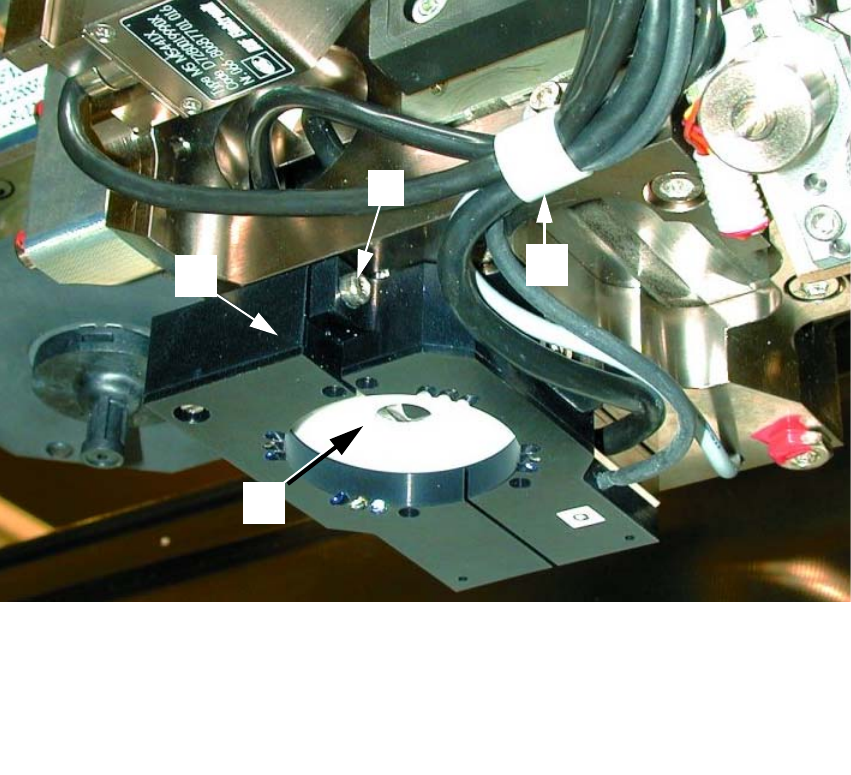
Abb. 2.2.3 Removing the Optional Oblique Illumination (Using S-25HM as an Example)
2
: Undo the cable clip fastener (see Abb. 2.2.3 -> 2).
: Hold onto the oblique illumination:
Undo the attachment screw (socket hex head cap screw M3: see Abb. 2.2.3 -> 2) and pull the
oblique illumination straight down and off the camera.
: Cautiously put the oblique illumination to one side so that it won’t be damaged.
: Use a small mirror as an aid and HOLD onto the PCB camera:
Starting from the bottom, undo the screws fastening the PCB camera (3 socket hex head cap
screws M2, see Abb. 2.2.2 -> 4) and lower the PCB camera out.
: Set the PCB camera down carefully so that it won’t be damaged.
1 Subgantry PCB camera
2 Cable clip: Fastener = 1 socket hex head cap screw M3
3 Optional oblique illumination
4 Fastener for oblique illumination: an attachment screw (socket hex head cap screw M 3))
3
1
2
4