00194313-03.pdf - 第76页
2 Assembly Instructions for PCB Camera, Multicolor SIPLACE S-25 HM / S-27 HM 2.3 Configuration PCB Camera Multicolor on LC 02/2007 Edition 76 : The field "PCB camera Mu lticolor" is deactivated. Activate the o …
SIPLACE S-25 HM / S-27 HM 2 Assembly Instructions for PCB Camera, Multicolor
02/2007 Edition 2.3 Configuration PCB Camera Multicolor on LC
75
2.3 Configuration PCB Camera Multicolor on LC
The software version 502.01 or later is a prerequisite for using the PCB camera Multicolor. 2
The optional PCB camera Multicolor is selected for SIPLACE 80 S-25 HM or HS-50 in the station
configurator of the UNIX line computer (LC). Insofar as this operation is concerned it can occur
before or after the PCB camera Multicolor is selected at the station in question, in the SITEST pro-
gram 502.xx. 2
: In the menu bar at the top, select "Services".
: In the pull-down menu that opens, select the option: "Station configuration".
: The window from which the machine is selected opens:
Select the machine on which the optional PCB camera Multicolor was installed.
: The "Main view of "Structure editor" is displayed automatically.
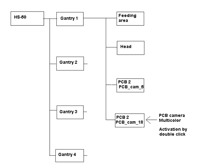
The selected machine is displayed graphically, arranged by gantries (1 to 2 or 4), and with the
pertinent substructures (component feeding areas, placement heads, PCB cameras, options,
etc.).
Abb. 2.3.1 Structural Overview, Example Using HS-50
2 Assembly Instructions for PCB Camera, Multicolor SIPLACE S-25 HM / S-27 HM
2.3 Configuration PCB Camera Multicolor on LC 02/2007 Edition
76
: The field "PCB camera Multicolor" is deactivated. Activate the optional PCB camera Multicolor
with a double click on "LP PC_cam _18", as illustrated above.
: Do this for all 4 / 2 gantries (HS-50 / S-25 HM).
: In the menu bar at top, in the Station Editor, select "File" -> "Save" - END".
: Then select: "File" -> "Data manager".
: Double click on the ICONs for "Master data".
: In the window that opens, double click on "Stations".
: Click once on the "Double click" field that opens and click once on "Compiler" to select it
and
: continue with a double click to select the pertinent station at which the PCB camera Multicolor
is used / was assemblied.
: In the "Data manager" window select the field "OK".
All of the windows are closed.
This concludes the work on the line computer for the configuration of the PCB camera Multi-
color. If you have not done so already, carry out the check "Camera Focus.... Substrate thick-
ness" as described in Abschn. 2.3.1. After this step continue with the activation/ configuration
and the illumination check (see Abschn. 2.4).
2
2
2
2
2
2
2
2
2
2
2
2
2
2
2
SIPLACE S-25 HM / S-27 HM 2 Assembly Instructions for PCB Camera, Multicolor
02/2007 Edition 2.3 Configuration PCB Camera Multicolor on LC
77
2.3.1 Camera Focus, dependent on PCB/Substrate Thickness
The focus level for the current substrate or PCB thickness can be optimized by installing or remo-
ving the distance plate (spacer) between the Multicolor PCB camera and camera holder. 2
The decision as to whether or not to work with the distance plate can be made during the course
of the assembly on the basis of the table (see Abschn. 2.2.2). As a final check, a specification can
be accessed at the line computer as described below: 2
: After describing the PCB, including entering the PCB/substrate thickness (= height) in the clu-
ster editor, conducting the produceability check and specifying the job for the relevant station
in the job editor you can check under -> Services -> Error messages.
If a change must be made involving the distance plate (spacer), a message such as the follo-
wing one is displayed:
Warning: PCB xxx.la is more than 3.400 mm thick (x.y > 3.400 mm)
For this reason, camera 18 must be mounted without the spacer.
or
Warning: PCB xxx.la is less than 1.500 mm thick (x.y < 1.500 mm).
For this reason, camera 18 must be mounted with the spacer.
xxx.la = name of PCB
x.y = in the cluster editor entered thickness (height) of the PCB / substrate
Camera 18 = PCB camera Multicolor
: Continue with the activation / configuration and the illumination check (see Abschn. 2.4).