00194313-03.pdf - 第74页
2 Assembly Instructions for PCB Camera, Multicolor SIPLACE S-25 HM / S-27 HM 2.2 Installing PCB Camera Board and PC B Camera Multicolor 02/2007 Edition 74 2.2.4 Laying Cables, Plugging into PC B Camera Board and V ision …
SIPLACE S-25 HM / S-27 HM 2 Assembly Instructions for PCB Camera, Multicolor
02/2007 Edition 2.2 Installing PCB Camera Board and PCB Camera Multicolor
73
2.2.3 Installing the "PCB Camera Board, Modular" from the Assembly Kit
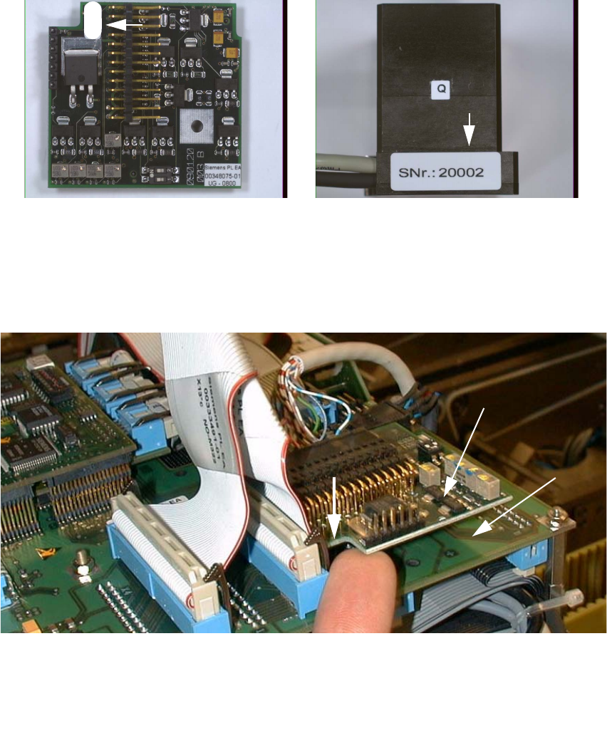
: Check the serial number of the PCB camera board, modular: It must correspond to the number
on the Multicolor PCB camera. Per gantry this allocation must be maintained during installa-
tion. The position of the number is shown in the following illustration.
Abb. 2.2.6 Check: Identical Serial Number on Modular PCB Camera Board and PCB Camera Multicolor
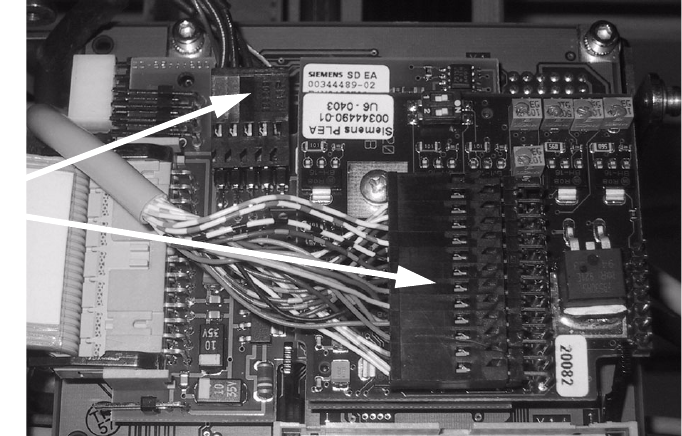
: Screw the distance holders of the assembly kit on the "vision board modular".
: Plug the "PCB camera board, modular" onto the "Vision board, modular" in the correct position,
as shown above.
2
Abb. 2.2.7 Installing the "PCB Camera Board, Modular" from Assembly Kit (Using HS-50 as an Example)
: Fix the PCB board modular.
1 Head PCB HS-50 assembly (modular)
2 PCB camera board, modular, manufacturer = Sticksel
3 Position of the recess
20002
3
2
1
2 Assembly Instructions for PCB Camera, Multicolor SIPLACE S-25 HM / S-27 HM
2.2 Installing PCB Camera Board and PCB Camera Multicolor 02/2007 Edition
74
2.2.4 Laying Cables, Plugging into PCB Camera Board and Vision Board
: Run the two cables from the PCB camera Multicolor up to the head PCBs.
: Plug the connectors of the PCB camera Multicolor into the "Vision board modular" and into the
"PCB camera, modular" located above it.
2
: Fasten the cables running upward such that the strain on the connectors is relieved.
: Plug the ribbon cables.
2.2.5 Assembling the Placement Head and the Machine
: Place the covers previously removed back on the placement heads. Fasten the covers with 5
screws each.
: Place the covers on to cable pits.
: Re-install the servo unit (socket hex head cap screw M5).
: Apply screw-locking compound to the screw.
: Remove all of the tools, etc., from the machine’s working area.
: Mount the feeder covers.
: Turn the machine on at the main switch. The compressed air must be connected.
: Dock all movable component changeover tables with the previous allocation.
: Close the safety doors and safety hoods.
Connect
camera cables
SIPLACE S-25 HM / S-27 HM 2 Assembly Instructions for PCB Camera, Multicolor
02/2007 Edition 2.3 Configuration PCB Camera Multicolor on LC
75
2.3 Configuration PCB Camera Multicolor on LC
The software version 502.01 or later is a prerequisite for using the PCB camera Multicolor. 2
The optional PCB camera Multicolor is selected for SIPLACE 80 S-25 HM or HS-50 in the station
configurator of the UNIX line computer (LC). Insofar as this operation is concerned it can occur
before or after the PCB camera Multicolor is selected at the station in question, in the SITEST pro-
gram 502.xx. 2
: In the menu bar at the top, select "Services".
: In the pull-down menu that opens, select the option: "Station configuration".
: The window from which the machine is selected opens:
Select the machine on which the optional PCB camera Multicolor was installed.
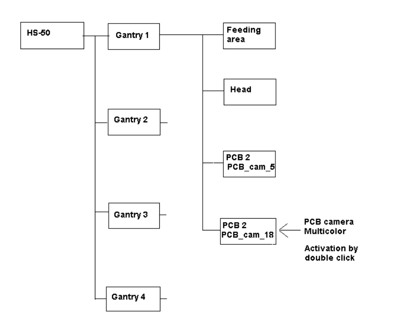
: The "Main view of "Structure editor" is displayed automatically.
The selected machine is displayed graphically, arranged by gantries (1 to 2 or 4), and with the
pertinent substructures (component feeding areas, placement heads, PCB cameras, options,
etc.).
Abb. 2.3.1 Structural Overview, Example Using HS-50