00194313-03.pdf - 第60页
2 Assembly Instructions for PCB Camera, Multicolor SIPLACE S-25 HM / S-27 HM 2.5 Preparatory Steps 02/2007 Edition 60 2.5.1.1 Conducting the Wiring in the T erminal Pane l, Right Side : Remove the cover from the horizont…

SIPLACE S-25 HM / S-27 HM 2 Assembly Instructions for PCB Camera, Multicolor
02/2007 Edition 2.5 Preparatory Steps
59
: The required top hat rail was not as yet installed in the terminal panel, right, on machines
S-25 HM, built from September to December 1998. Install this rail as follows:
WARNING
No chips are to be allowed to find their way into the electrical units during the following drilling.
To reliably preclude the possibility of damage to cables on the back of the partition during the dril-
ling the drill should not project further into the metal sheet than the thickness of the sheet (= 4 mm).
It´s the best to use a spacer. 2
: Cover the electrical units in the terminal panel carefully so that no chips can find their way in
during the following drilling. Use pieces of tape to fasten a cloth of adequate size over the ter-
minal panel such that only the assembly surface for the DIN mounting rail is not covered (see
Fig. 2.6.2).
: Hold the DIN mounting rail in the position on the back of the terminal panel as shown in Fig.
2.6.2 and mark the 2 fastening holes for the slots.
: Cut two holes with M4 threads.
: Fasten the DIN mounting rail on the back of the terminal panel (2 washers, 2 socket hex head
cap screws M4).
: Clip the 50 V voltage regulator module (= converter, Item no. 00349095-01, see assembly kit:
Section 2.4.1) onto the top hat rail on the RH side.
: Clip the relay K1 left, onto the top hat rail next to the voltage regulator module.
: Remove the cloth carefully and clean the entire area with a vacuum cleaner. This includes the
floor under the side guard (area of the component changeover table).
: Continue the work by removing the covers over the cable pit (see below).

2 Assembly Instructions for PCB Camera, Multicolor SIPLACE S-25 HM / S-27 HM
2.5 Preparatory Steps 02/2007 Edition
60
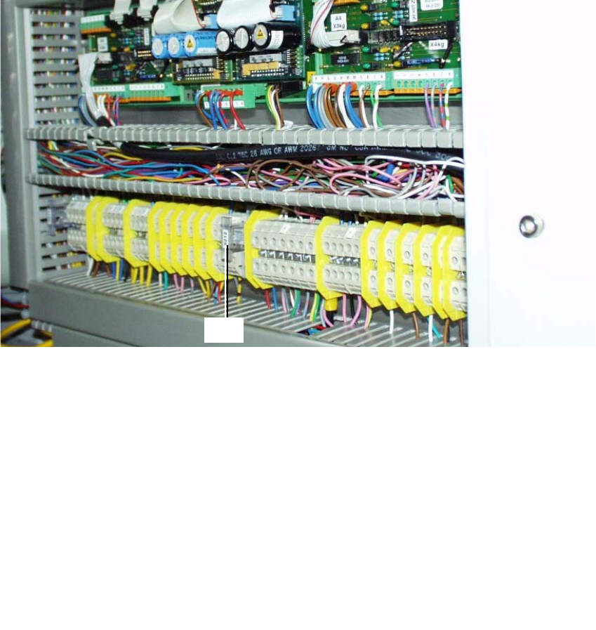
2.5.1.1 Conducting the Wiring in the Terminal Panel, Right Side
: Remove the cover from the horizontal and vertical cable pit.
: Remove the green strand running from rectifier module A2: X7 to terminal X207-1
(layout A2: see Fig. 2.6.2). The terminal X207-1 is then not in use.
: Run the cables W1 to W5 from the assembly kit as shown in the overview, Fig. 2.13.7.
Prefabricate the cables as much as possible.
NOTE:
You will need a size 1 screwdriver to disconnect and make the Catch terminal connections and
terminal connections X 207. 2
: Lay and wire the new cables W1 to W5 as shown in circuit diagram Fig. 2.13.8 AND, while
doing so, assemble cables W2 and W3 as follows:
: Install a twin connector sleeve at cable end W2 that will be connected to X207-3 and at cable
end W3 that will be connected to X207-5.
: Use the crimp pliers to fasten each of the two strands bl/bk in the twin connector sleeve.
: Clamp the cables W2 thus assembled to X 207-3 and W3 to X 207-5.
: Make certain that all connections are firmly seated and are correctly allocated.
2
SIPLACE S-25 HM / S-27 HM 2 Assembly Instructions for PCB Camera, Multicolor
02/2007 Edition 2.5 Preparatory Steps
61
2.5.2 Assembly in the Terminal Panel, LH Side
2.5.2.1 Changing the "Illumination" Cables
The S-25 HM / S-27 HM have 2 "illumination" cables: 2
– Cable "illumination, gantry 1": Item no. 00244260-xx
– Cable "illumination, gantry 2": Item no. 00244261-xx
These cables must be changed first, as described below.
Fig. 2.5.3 Terminal Panel, LH Side, Layout of the Illumination Cables, Gantries 1 and 2
: Open the machine frame doors for terminal panel, LH side.
: Use the circuit diagram Fig. 2.13.6 and Change the two cables "illumination, gantry 1" and "2"
as follows:
: Separate the strands wh, gn, gr, bl which are clamped to terminal X212 - 4 with a connector
sleeve.
: Use the crimping pliers. Now clamp these strands separately as follows, each in a twin con-
nector sleeve from the assembly kit (Section 2.4.1): wh with gn. gr with bl.
: Clamp the 2 changed "Illumination" cables on the terminal panel:
2
2
the strands wh, gn
-> to terminal X212 - 4 (+ 24V),
the strands gn, bl -> to terminal X212 - 9 (+ 50V)
3
4
X212