00194313-03.pdf - 第67页
SIPLACE S-25 HM / S-27 HM 2 Assembly Inst ructions for PCB Camera, Multicolor 02/2007 Edition 2.5 Preparatory Steps 67 2 Fig. 2.14 - 2 T erminal block on the right-hand side 2 No additional wiring is required . The conne…
2 Assembly Instructions for PCB Camera, Multicolor SIPLACE S-25 HM / S-27 HM
2.5 Preparatory Steps 02/2007 Edition
66
2.5.4 S-27 HM wiring with new terminal block
: Open the vertical cable duct on the right.
: Remove the lamp-wire connector with the white, blue-black and blue wires.
2
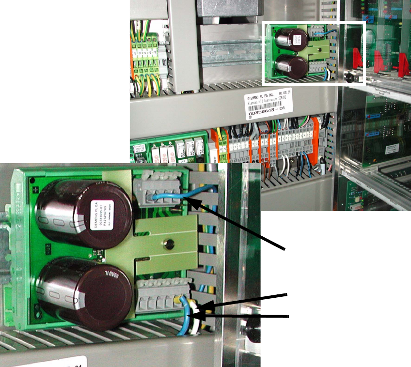
Fig. 2.14 - 1 Terminal block on left-hand side
2
: Clamp white wire from the lamp-wire connector to X6/6 (GND).
: Clamp blue-black wire from the lamp-wire connector to X6/5 (+24 V).
: Clamp blue wire from the lamp-wire connector to X7/1 (+50V).
2
2
2
X6/6
X6/5
X7/1
SIPLACE S-25 HM / S-27 HM 2 Assembly Instructions for PCB Camera, Multicolor
02/2007 Edition 2.5 Preparatory Steps
67
2
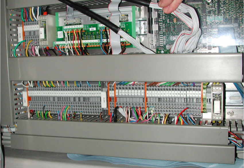
Fig. 2.14 - 2 Terminal block on the right-hand side
2
No additional wiring is required. The connections are prewired. 2
2
2
2
2 Assembly Instructions for PCB Camera, Multicolor SIPLACE S-25 HM / S-27 HM
2.2 Installing PCB Camera Board and PCB Camera Multicolor 02/2007 Edition
68
2.2 Installing PCB Camera Board and PCB Camera
Multicolor
At S-25 HM possibly the modular head PCB assembly is not installed yet. 2
2
Abb. 2.2.1 Conversion PCB "small axis" still installed (= old PCB version)
: If the conversion PCB "small axis" is still installed on the placement head, assembly the mo-
dular head PCB unit now on the basis of its own assembly instructions (see chapter "Require-
ments").
At S-27 HM the modular head PCB assembly is always installed. 2
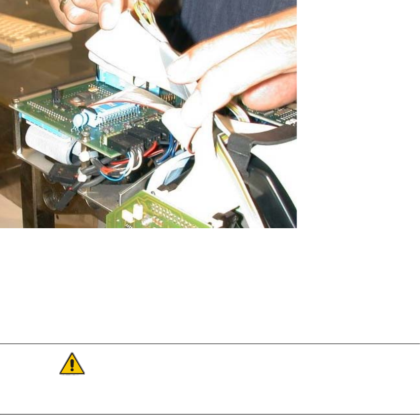
CAUTION
Comply the ESD regulations during the following handling of the PCBs.
Make certain that no screws or other parts drop into the machine or the placement head !! 2