00194313-03.pdf - 第58页
2 Assembly Instructions for PCB Camera, Multicolor SIPLACE S-25 HM / S-27 HM 2.5 Preparatory Steps 02/2007 Edition 58 : Open the machine frame door s on the terminal p anel, right side. : Loosen th e screw faste ning the…
SIPLACE S-25 HM / S-27 HM 2 Assembly Instructions for PCB Camera, Multicolor
02/2007 Edition 2.5 Preparatory Steps
57
2.5 Preparatory Steps
: Open the safety hoods.
: Remove the reject bin.
: Disassemble the cover of the feeder modules.
: Undock the movable component changeover tables
: Turn the machine OFF at the main switch, isolate the machine from the mains, turn OFF the
flow of compressed air at the compressed air uni
: Push the X-gantries toward the outside of the machine so that the placement heads are readily
accessible.
2.5.1 Assembly in the Terminal Panel, Right Side
NOTE:
Ascertain you before starting assembly, what kind of clamping field is in the machine
see chapters 2.5.1, 2.5.3 and 2.5.4. 2
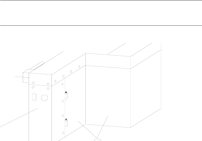
Abb. 2.5.1 Opening the Machine Frame Doors (Service Cabinets for Terminal Panel, Right Side)
Key:
1. Machine frame doors
2. Lateral protection (remains installed)
2 Assembly Instructions for PCB Camera, Multicolor SIPLACE S-25 HM / S-27 HM
2.5 Preparatory Steps 02/2007 Edition
58
: Open the machine frame doors on the terminal panel, right side.
: Loosen the screw fastening the servo unit (loosen the M5 socket hex head screw) and lift the
servo unit out.
2
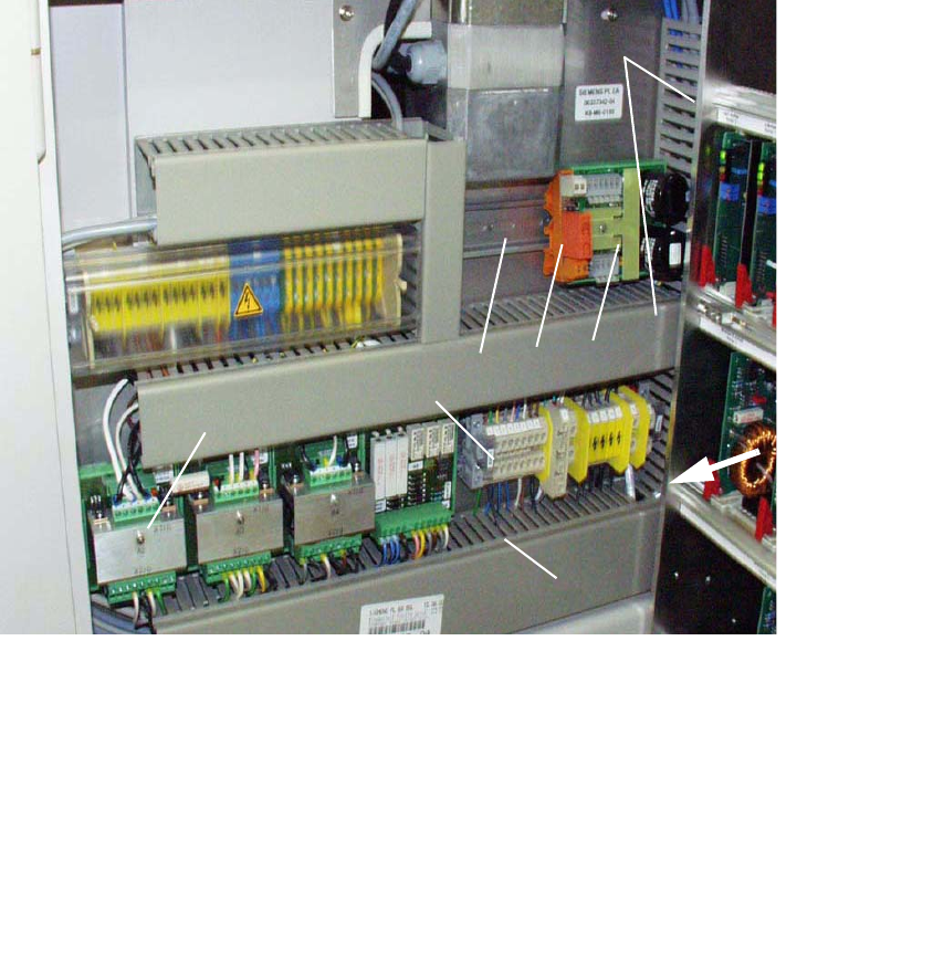
Abb. 2.5.2 Terminal Panel, RH Side: X207; Location for Install. Voltage Module 50 V + Relay K1
2
2
2
2
2
2
1 Servo-unit (remove)
2 Cable pits: remove cover
3 Top hat rail (install, if necessary)
Fasteners: 2 washers A4.2 and 2 socket hex head cap screws M4
4 50 V voltage regulator module 50 S-25 HM / F5 HM
5 Relay K1 S-25 HM / F5 HM
6 Terminal strip X207
7 Rectifier module A2
1
2
4
5
3
6
2
7

SIPLACE S-25 HM / S-27 HM 2 Assembly Instructions for PCB Camera, Multicolor
02/2007 Edition 2.5 Preparatory Steps
59
: The required top hat rail was not as yet installed in the terminal panel, right, on machines
S-25 HM, built from September to December 1998. Install this rail as follows:
WARNING
No chips are to be allowed to find their way into the electrical units during the following drilling.
To reliably preclude the possibility of damage to cables on the back of the partition during the dril-
ling the drill should not project further into the metal sheet than the thickness of the sheet (= 4 mm).
It´s the best to use a spacer. 2
: Cover the electrical units in the terminal panel carefully so that no chips can find their way in
during the following drilling. Use pieces of tape to fasten a cloth of adequate size over the ter-
minal panel such that only the assembly surface for the DIN mounting rail is not covered (see
Fig. 2.6.2).
: Hold the DIN mounting rail in the position on the back of the terminal panel as shown in Fig.
2.6.2 and mark the 2 fastening holes for the slots.
: Cut two holes with M4 threads.
: Fasten the DIN mounting rail on the back of the terminal panel (2 washers, 2 socket hex head
cap screws M4).
: Clip the 50 V voltage regulator module (= converter, Item no. 00349095-01, see assembly kit:
Section 2.4.1) onto the top hat rail on the RH side.
: Clip the relay K1 left, onto the top hat rail next to the voltage regulator module.
: Remove the cloth carefully and clean the entire area with a vacuum cleaner. This includes the
floor under the side guard (area of the component changeover table).
: Continue the work by removing the covers over the cable pit (see below).