Maintenance Manual.pdf - 第152页
AV131 MAINTENANCE MANUAL 7.6 I nserti on Head Un i t D79MEC- Z1-M 00-A0 7.6- 5 7.6. 3 Inserti on Unit Drive Unit No. N610052015A A Inspection Perio d No . Item T ask Descrip ti on Make sure t hat t he be l t is not w o…

AV131
MAINTENANCE MANUAL
7.6 Insertion Head Unit
D79MEC-Z1-M00-A0
7.6-4
Oiling
Period No. Item Task
Oiling
volume
Description
1. Pusher Position: Up/down sliding surfaces
2. Insertion guide
0.05 cm
3
3. Slide cam 0.05 cm
3
4. Guide
5. Guide base
6. Roller and slide cam
7. Pin and block lever
8.
Pin, lever and guide
base
0.02 cm
3
9.
Pin, bracket and
bending die
0.01 cm
3
Position: Sliding surface
10. Pusher
11. Insertion guide
0.02 cm
3
Position: Sliding surface in the direction of
pitch
Every
other
week
12.
Fitting surfaces
between the insertion
guide and the slide
cam
0.01 cm
3
Position: Fitting surface
AV131
MAINTENANCE MANUAL
7.6 Insertion Head Unit
D79MEC-Z1-M00-A0
7.6-5
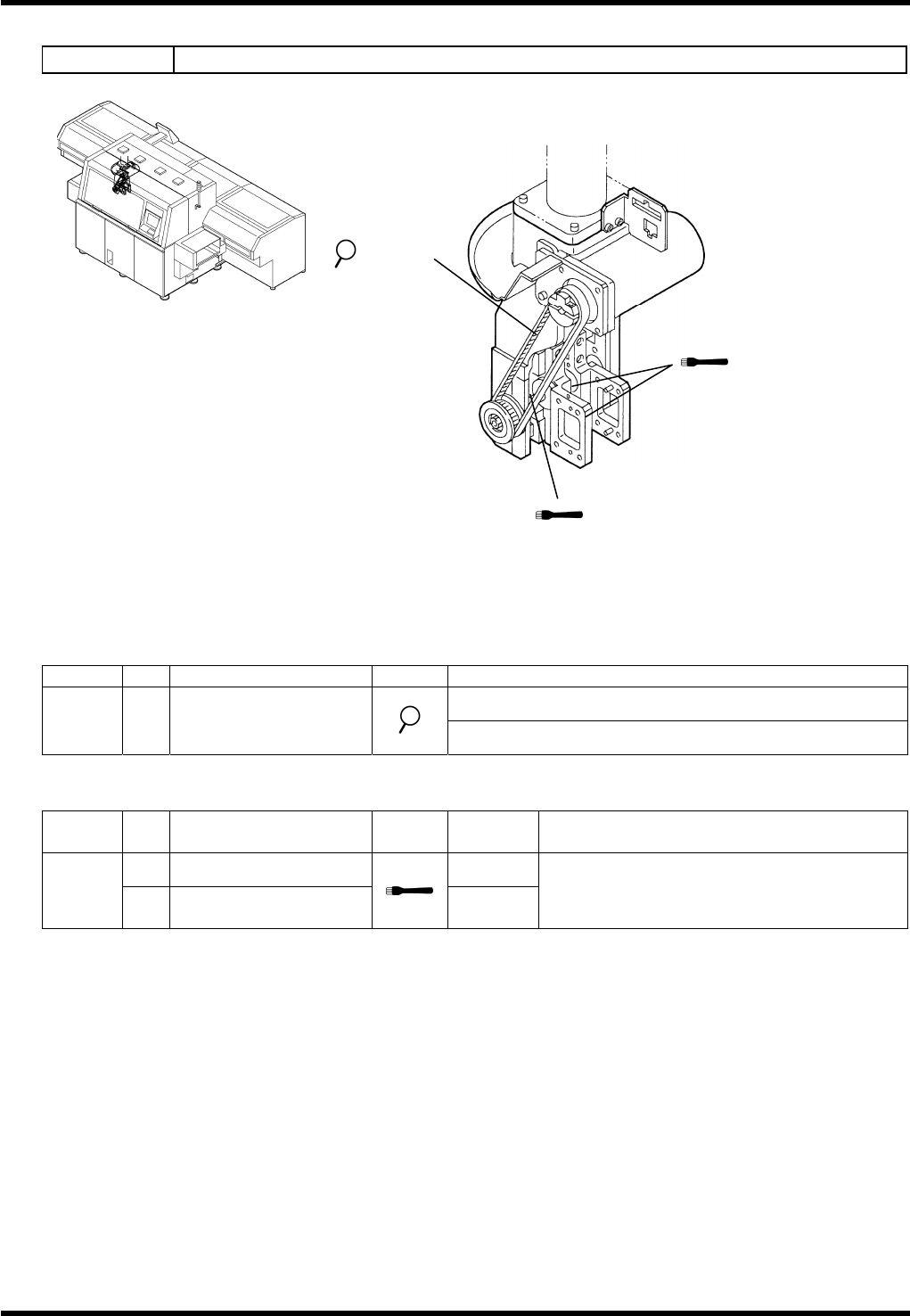
7.6.3 Insertion Unit Drive
Unit No. N610052015AA
Inspection
Period No. Item Task Description
Make sure that the belt is not worn or damaged.
3
months
a. Belt
Make sure that belt tension is properly adjusted.
Oiling
Period No. Item Task
Oiling
volume
Description
1. Ball screw 0.5 cm
3
Every
other
week
2. LM guide (2 areas)
0.1 cm
3
each
Apply grease after removing all foreign
matters.
2. LM guide
a. Belt
1. Ball screw
AV131
MAINTENANCE MANUAL
7.6 Insertion Head Unit
D79MEC-Z1-M00-A0
7.6-6
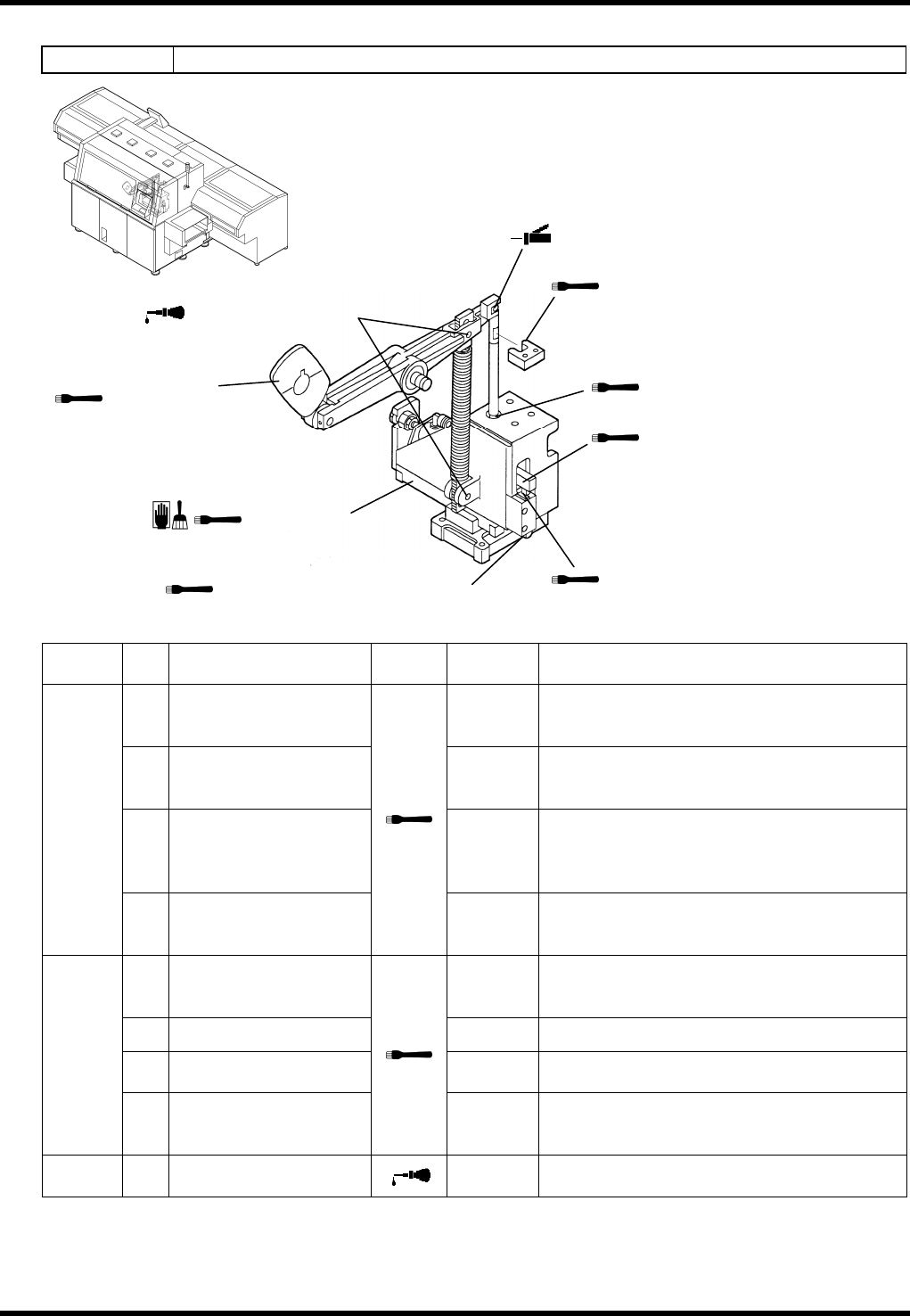
7.6.4 JW Head Drive Unit (Option)
Unit No. 1087120000
Oiling
Period No. Item Task
Oiling
volume
Description
2.
Sliding surfaces
between the cam
follower and the rod
0.5 cm
3
4.
Sliding surfaces
between the shaft and
the block.
0.1 cm
3
5.
Sliding surfaces
between the rod and
the bush (Insertion
Head) (2 areas)
0.1 cm
3
each
Every
other
week
6.
Sliding surfaces
between the shaft and
the cam follower
0.1 cm
3
1.
Sliding surfaces
between the guide and
the rod
0.1 cm
3
3. Cam surface 0.5 cm
3
Position: Periphery
7.
LM guide (2 units: front
and rear)
0.6 cm
3
each
Position: Rail surface
Monthly
8.
Contacting surfaces
between the shaft and
the pusher
0.05 cm
3
3
months
9.
Spring support pin
(2 positions)
0.5 cm
3
2. Sliding surfaces between the cam
follower and the rod
7. LM guide
3. Cam surface
5. Sliding surfaces between
the rod and the bush
6. Sliding surfaces between the
shaft and the cam follower
4. Sliding surfaces between
the shaft and the block.
8. Contacting surfaces between
the shaft and the pusher
9. Spring support pin
1. Sliding surfaces between
the guide and the rod