Maintenance Manual.pdf - 第41页
AV131 MAINTENANCE MANUAL 2.3 M aintenance F uncti on D79MEC- 10-030-A0 2.3- 6 2.3. 5 Error Messages 1. 1. When the maint enance sw i tc h is tur ned O N to engage the maint enance mode: T he background of the mai n m enu…
AV131
MAINTENANCE MANUAL
2.3 Maintenance Function
D79MEC-10-030-A0
2.3-5
2.3.4 Operational Restrictions
Inhibited Operations (Cannot be Stopped Unless Operating Intentionally)
Origin return of all axes
Axis positioning from the Machine adjust - NC MOVE screen
XY axis positioning from the Auto Camera Scale Measurement screen
XY axis positioning from the Board 2 Holes Teaching screen
Z axis positioning by pressing “MOVE WAITING POSITION” on the feeder carriage control panel
Origin return of the rail axis
Positioning of the rail axis from the Machine adjust - Width MOVE screen
Automatic width adjustment from the PCB Data Select screen
Automatic width adjustment from the PCB Data Edit screen
Rail width adjustment from the PCB Data Teaching screen
Any axis operation during production
Permissible Operations (Can be Stopped If Quitting Operation)
Release of safety stop by pressing <START>
Teaching of each axis from the Machine adjust - NC JOG screen (low speed)
Teaching of the XY axis from the Binary Level Setting screen (low speed)
Teaching of the XY axis from the Manual Camera Scale Measurement screen (low speed)
Teaching of the XY axis from the Auto Camera Scale Measurement screen (low speed)
Teaching of the XY axis from the Board 2 Holes screen (low speed)
Teaching of the rail axis from the Machine adjust - Width JOG screen (low speed)
Teaching of the rail axis from the Board Data Teaching screen (low speed)
AV131
MAINTENANCE MANUAL
2.3 Maintenance Function
D79MEC-10-030-A0
2.3-6
2.3.5 Error Messages
1.
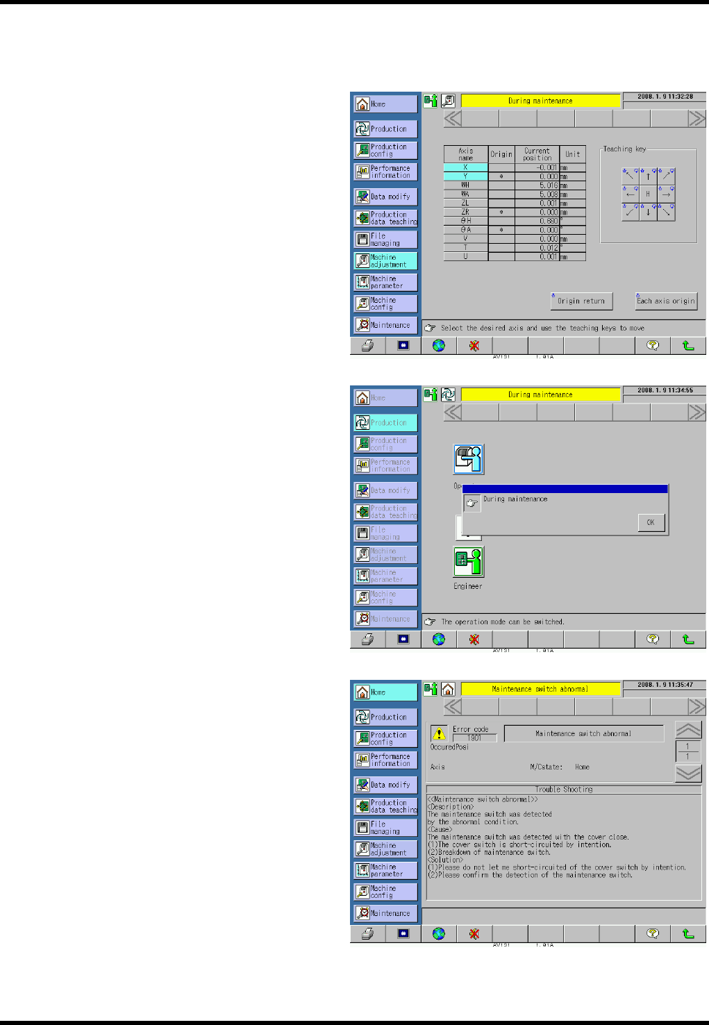
1. When the maintenance switch is turned ON to engage the maintenance mode:
The background of the main menus turns
yellow and the message “During
maintenance” appears to notify the
operator that the maintenance switch is
turned ON and the maintenance mode is
engaged.
2. When [Production] is pressed in the
maintenance mode:
A pop-up window indicating “During
maintenance” appears. Pressing [OK]
returns the display forcibly to the screen
immediately before [Production] is pressed.
3. Other
The following error occurs if the
maintenance switch is turned ON after
closing the safety covers, clearing a safety
stop error and closing all covers (all safety
interlock switches are ON and safety stop
error has been cleared (e.g., when the
maintenance switch has been broken)).
Error code: 1901
Error name: Maintenance switch abnormal
Check the maintenance switch for
detection status.

AV131
MAINTENANCE MANUAL
2.4 Safety Standards
D79MEC-10-040-A0
2.4-1
2.4. Safety Standards
D79MEC-10-040-A0
2.4.1 Applied Standards
This machine is a CE-marked product, which complies with the following standards.
However, for the machines to be delivered to countries where CE marking is not required, modification may
be made according to the custom specification.
Note that, in such a case, the machine may not satisfy the requirements for CE marking any more.
Machinery Directive : 98/37/EC
EN ISO 12100-1 (2003): Safety of machinery - Basic concepts, general principles for design
Part 1: Basic terminology, methodology
EN ISO 12100-2 (2003): Safety of machinery - Basic concepts, general principles for design
Part 2: Technical principles and specifications
EN 60204-1 (1997): Safety of machinery - Electrical equipment of machines
Part 1: General requirements
EMC Directive: 89/336/EEC as amended by 92/31/EEC and 93/68/EEC
EN 55011 (1998) A1: 1999, A2: 2002
Limits and methods of measurement of radio disturbance characteristics of
industrial, scientific and medical (ISM) radio-frequency equipment
EN 61000-6-2 (2001): Electromagnetic compatibility. Generic immunity standard.
Part 2: Industrial environment
Low Voltage Directive: 73/23/EEC as amended by 93/68/EEC