JUKI FX-3R MAINTENANCE GUIDE.pdf - 第10页
FX-3R Maintenance Guide 1-2 Rev. 1.00 1-1-1. X-Axis Magn escale Affixing Position (1) Affix the magnescale while guiding it using the X_MSC install jig. The affixing starting line for the LF/RF is indicated by the mark-o…
FX-3R Maintenance Guide
1-1
DANGER
To prevent any trouble caused by accidental machine start, always
shut-down the power before starting the maintenance and
adjustment work.
The XY-axis uses a very strong magnet.
• Do not put any metallic object close to the magnet surface. Once the
magnet attracts a metallic object, this object cannot be removed due to
strong magnetic force.
• Before starting the maintenance work, take off precision portable devices,
such as a wrist watch from your body.
• Do not allow personnel who uses a precision medical device, such as an
artificial cardiac pacemaker, etc to carry out the maintenance work.
[1] X-Y UNIT
1-1. Replacing the Magnescale
(1) Detach the magnescale head from the bracket.
(2) Peel off the old magnescale.
(3) Degrease the magnescale mounting surface and magnescale completely.
Note 1: Before replacing the magnescale, put the magnescale near the machine and leave
it for 1 hr. or longer to make the temperature of the magnescale similar to that of the
machine.
Note 2: “Mecha fine mate” is recommended for the degreasing agent.
Note 3: Deviation amount when compared to the specified value of the magnescale in the
X-direction:
±
0.1 mm or less.
Note 4: Do not put any magnet, such as magnetized screwdriver or support pin close to the
magnescale. Doing so may cause the magnescale to malfunction.
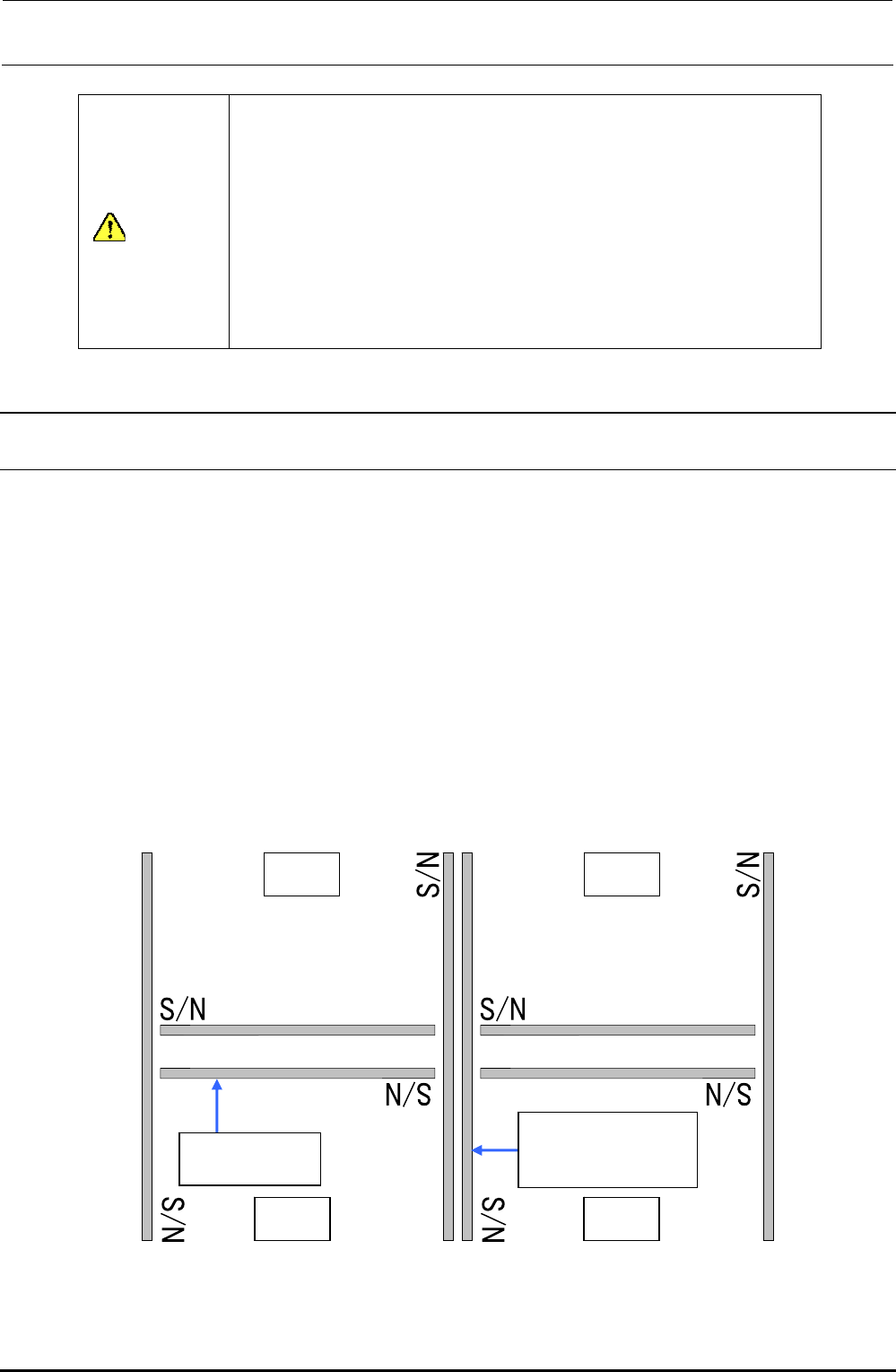
Note 5: The magnescale has a correct orientation. Affix it in the direction shown in the figure
below.
LR RR
LF RF
40091396
40048080(For XL)
Magnescale Y
40048026
Magnescale X
(∗ S/N: Serial No. of the magnescale)
Figure 1-1-1 Affixing Orientation of the Magnescale (Main Body Top View)
Rev. 1.00
FX-3R Maintenance Guide
1-2
Rev. 1.00
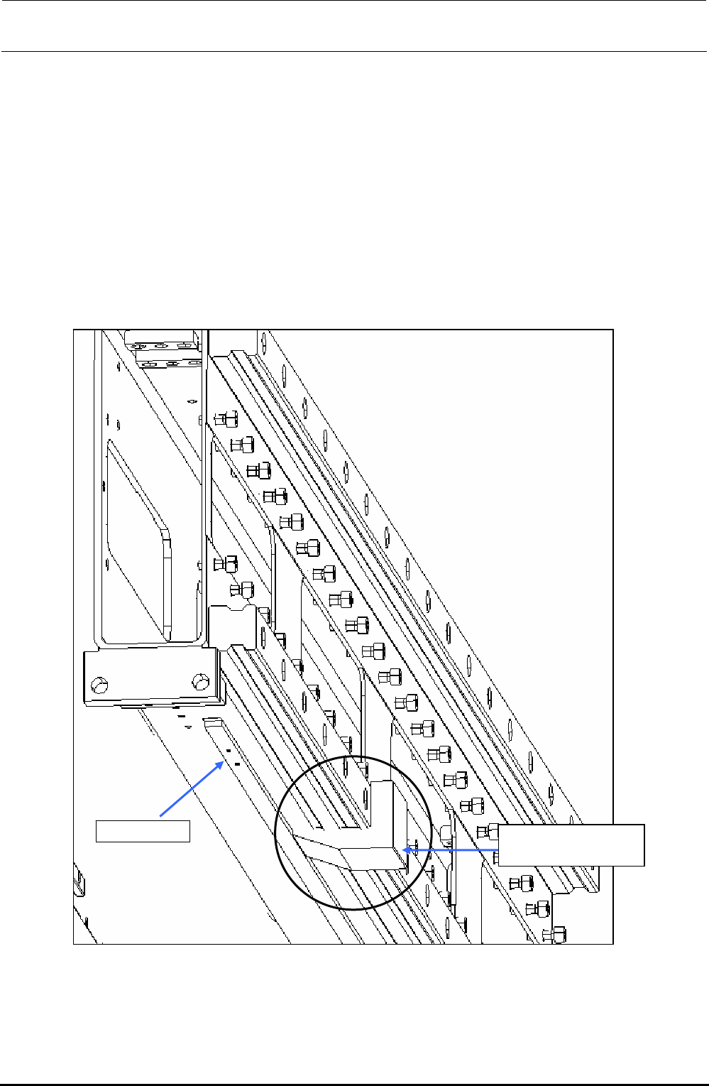
1-1-1. X-Axis Magnescale Affixing Position
(1) Affix the magnescale while guiding it using the X_MSC install jig.
The affixing starting line for the LF/RF is indicated by the mark-off line on the left side when
viewed from the front and that for the LR/RR is indicated by the mark-off line on the left when
viewed from the rear.
Adjust the position of the Z-phase marking on the magnescale side to the mark-off line, and
then affix the magnescale.
Specification value: Magnescale affixing position (Displacement in the direction parallel with the
head movement) ± 0.1mm
Figure 1-1-1-1 Mounting Example of X_MSC Install Jig
40069368
X_MSC install jig
Magnescale
FX-3R Maintenance Guide
1-3
Rev. 1.00
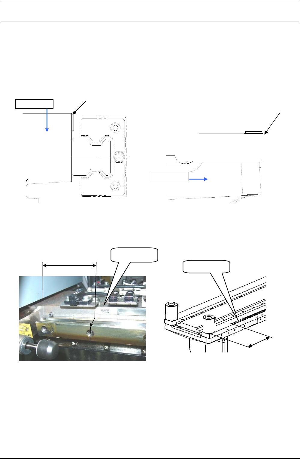
1-1-2. Y-Axis Magnescale Affixing Position
(1) Affix the magnescale while aligning the center portion with the top surface of the Y-frame C and
its side surface with the rail side surface of the Y-frame S.
Specification value: Magnescale affixing position (Displacement in the direction parallel with the
head movement) ± 0.1mm
Figure 1-1-2-1 Y-Axis Magnescale Affixing Position
(Left Figure shown above: Y-frame C, Right Figure shown above: Y-frame S)
Y-frame C
Y-frame S
Alignment with
this surface
Alignment with
this surface
Label side
72±1mm
Figure 1-1-2-2 Y-frame C Affixing Position
Figure 1-1-2-3 Y-frame S Affixing Position
115±1mm
Label side