JUKI FX-3R MAINTENANCE GUIDE.pdf - 第31页
FX-3R Maintenance Guide 2-13 2-6. Replacing the Z-Slide Shaft When the Z-slide shaft has been replaced, it is necessary to input the MS parameters related to the θ -axis and Z-axis home position adjustment, Z-axis height…
FX-3R Maintenance Guide
2-12
2-5. Replacing the Belts
2-5-1. Replacing the Timing Belt Z
After the timing belt Z has been replaced, it is absolutely necessary to re-input the MS parameters
related to the Z-axis home position adjustment, Z-axis height, and laser. (For details of input items,
see section 2-7.)
Rev. 1.00
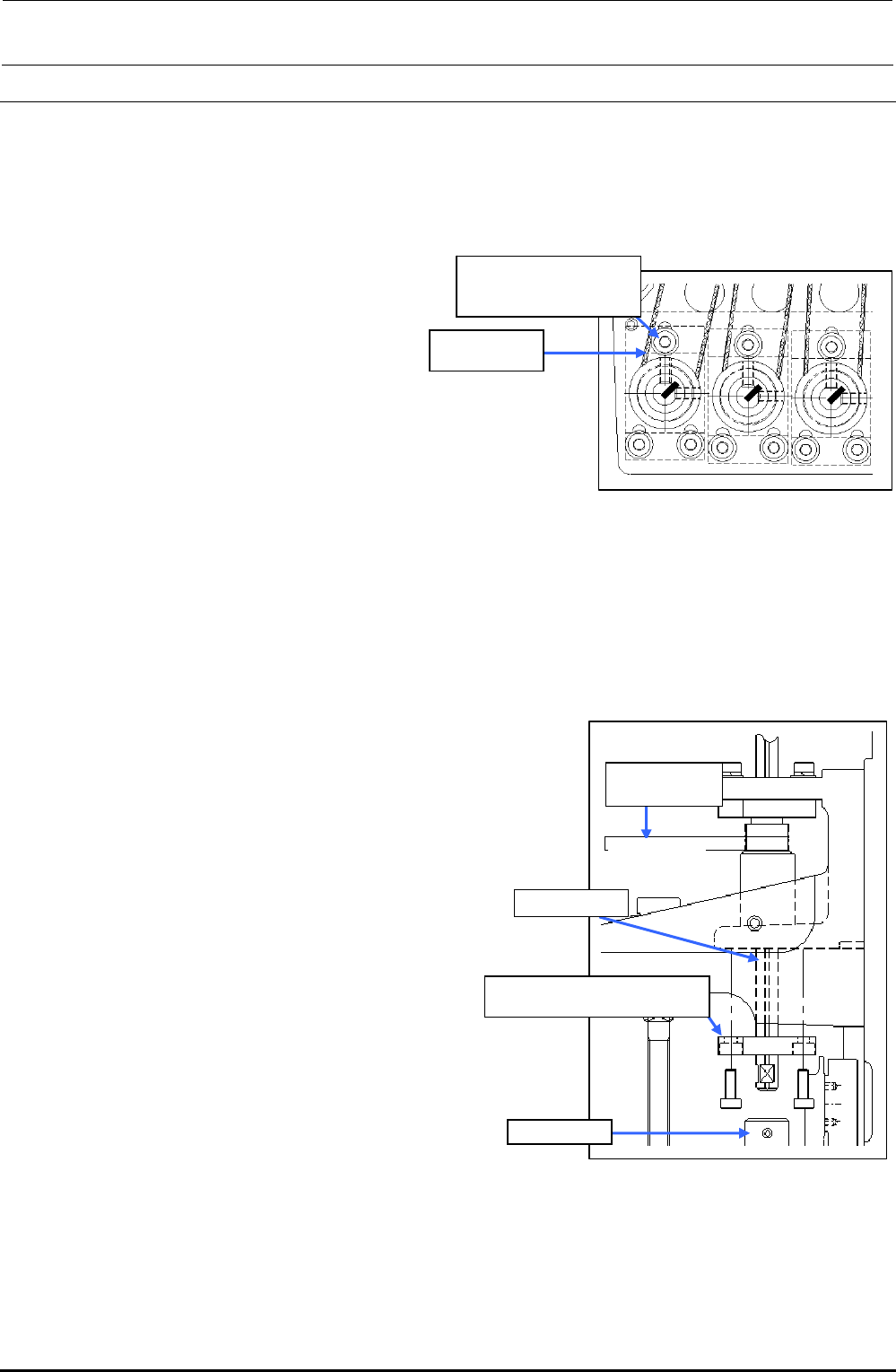
1) Loosen the SEMS cap bolts c (×3) shown
in the figure on the right.
2) Replace the timing belt Z.
3) Reassemble the components in the
reverse order of disassembly.
∗ Apply Loctite 242 to the Z-motor
mounting screws (3 pcs.) and tighten
them with a tightening torque of 2.3 N・m.
c SL6031692TN
SEMS cap bolt with
washer M3×16
40046522
Timing belt Z
Figure 2-5-1 Removing the Z-motor
∗ Adjust the belt tension following section 2-2-1.
2-5-2. Replacing the Timing Belt θ
After the timing belt θ has been replaced, it is absolutely necessary to re-input the MS parameters
related to the Z-axis home. (For details of input items, see section 2-7.)
1) Detach the bearing base c.
(L1 to L3: bearing base LL, L4 to L6: bearing base LR)
2) Detach the ball spline from the coupling d.
3) Pull out the spline housing downward and the spline
shaft upward.
4) Replace the timing belt θ.
5) Reassemble the components in the reverse
order of disassembly.
∗ When the bearing base L is secured, make sure that
the shaft is rotated smoothly.
∗ Adjust the belt tension following section 2-2-2.
L1 to L3: Bearing base LL c
L4 to L6: Bearing base LR c
Ball spline
Coupling d
40046521
Timing Belt T
Timing Belt θ
Figure 2-5-2 Replacing the
Timing Belt θ
FX-3R Maintenance Guide
2-13
2-6. Replacing the Z-Slide Shaft
When the Z-slide shaft has been replaced, it is necessary to input the MS parameters related to the
θ-axis and Z-axis home position adjustment, Z-axis height, and laser again.
(For details about input items, see section 2-7.)
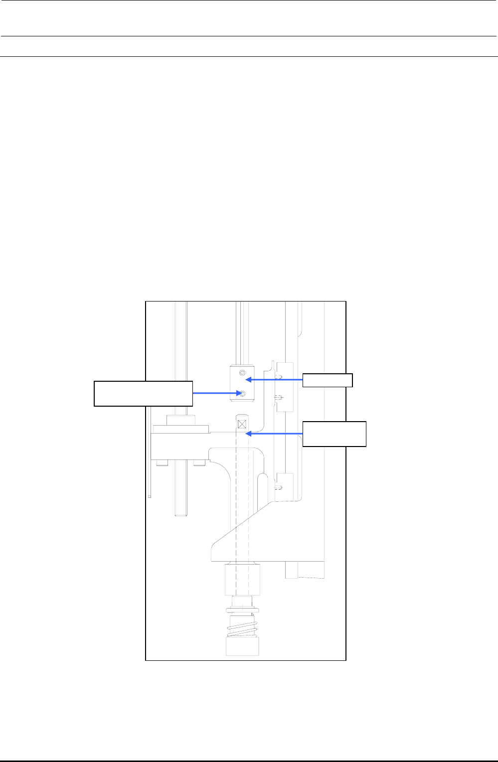
(1) Remove the hollow set screw c (×1) from the lower portion of the coupling.
(2) Detach the Z-slide shaft from the Z-slide bracket.
(3) Reassemble the components in the reverse order of disassembly.
∗ Secure the coupling with it kept pushed-in and make sure that any vertical play does not
exist on the slide shaft.
∗ When tightening the set screws of the coupling, align the flat part of the slide shaft with
the orientation of the coupling set screw. Tighten the set screw with a tightening torque of
0.5 N・m.
Rev. 1.00
c SM8030312TP
Set screw M3 L=3
Coupling
40044586
Z-slide Shaft
Figure 2-6-1 Z-slide Shaft
FX-3R Maintenance Guide
2-14
2-7. Readjustment After Replacement of Head Unit
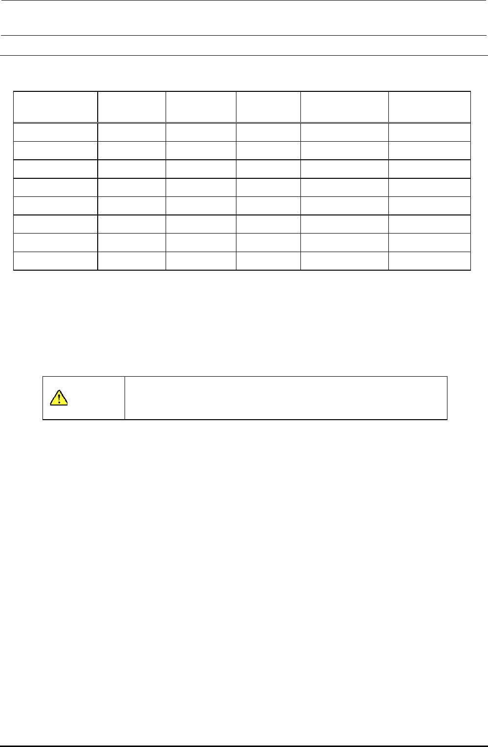
Table 2-7-1 List of Readjustment Items After Replacement of Head Unit
Laser ID No.
setup
Laser offset Head offset
Component speed
measurement
Mounting general
offset
Head unit assembly { { {
Z-motor {
θ-motor
{ {
Z-sensor {
LNC60 { { { { {
Timing belt Z {
Timing belt θ
{ {
Z-slide shaft { { {
The MS parameters must be input from the left in order.
When inputting a laser offset after the head unit assembly, Z-motor, and/or timing belt Z have been
replaced, obtain the laser offset again after the height of the top surface of the laser offset board has
been set to “0”. According to the offset value before replacement, the offset cannot be obtained
correctly or it cannot be obtained automatically.
CAUTION
To prevent any personal injury, do not put your hand inside the
machine or your face or head close to the machine during operation
of the touch panel and/or HOD.
Rev. 1.00