JUKI FX-3R MAINTENANCE GUIDE.pdf - 第116页
FX-3R Maintenance Guide 10-1 DANGER To prevent any trouble caused by accidental machine start, always shut-down the power before starting the maintenance and adjustment work. [10] SWITCHES 10-1. Replacing the Push-Button…
FX-3R Maintenance Guide
9-10
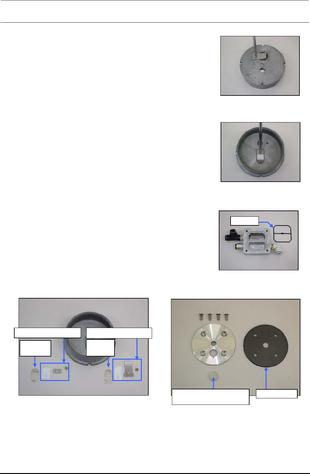
<Detaching/replacing the cylinder detailed parts>
1) Loosen the round head screws (M3 × L5) fixing the
exhaust valve support plate.
2) Detach the exhaust valve support plate, exhaust valve
backup, and exhaust valve.
Figure 9-4-14 Removing the Round
Head Screws
3) Loosen the round head screws (M3 × L5) fixing the
suction valve support plate.
4) Detach the suction valve support plate, exhaust valve
backup, and suction valve.
Figure 9-4-15 Removing the Round
Head Screws
5) Remove the gasket from the head cover and wash the
head cover. After the washing has been completed,
blow the air to the head cover and replace the gasket
with a new one.
Gasket
Figure 9-4-16 Gasket
6) Wipe off the washing solution with a cloth rag and degrease the entire cylinder completely.
Suction
valve
∗
Exhaust
valve
∗
Exhaust valve backupSuction valve backup
Suction valve interference
prevention rubber
Cup packing
Figure 9-4-17 Cylinder Figure 9-4-18 Support Plate and Cup Packing
∗ The same part is used for both the suction valve and the exhaust valve.
7) Replace each consumable part with a new one. Reassemble the parts and components in the
reverse order of disassembly so that they meet the markings. At this time, tighten the M6 bolts
fixing the head cover with a tightening torque of 8N⋅m.
Rev. 1.00
FX-3R Maintenance Guide
10-1
DANGER
To prevent any trouble caused by accidental machine start, always
shut-down the power before starting the maintenance and
adjustment work.
[10] SWITCHES
10-1. Replacing the Push-Button Switch
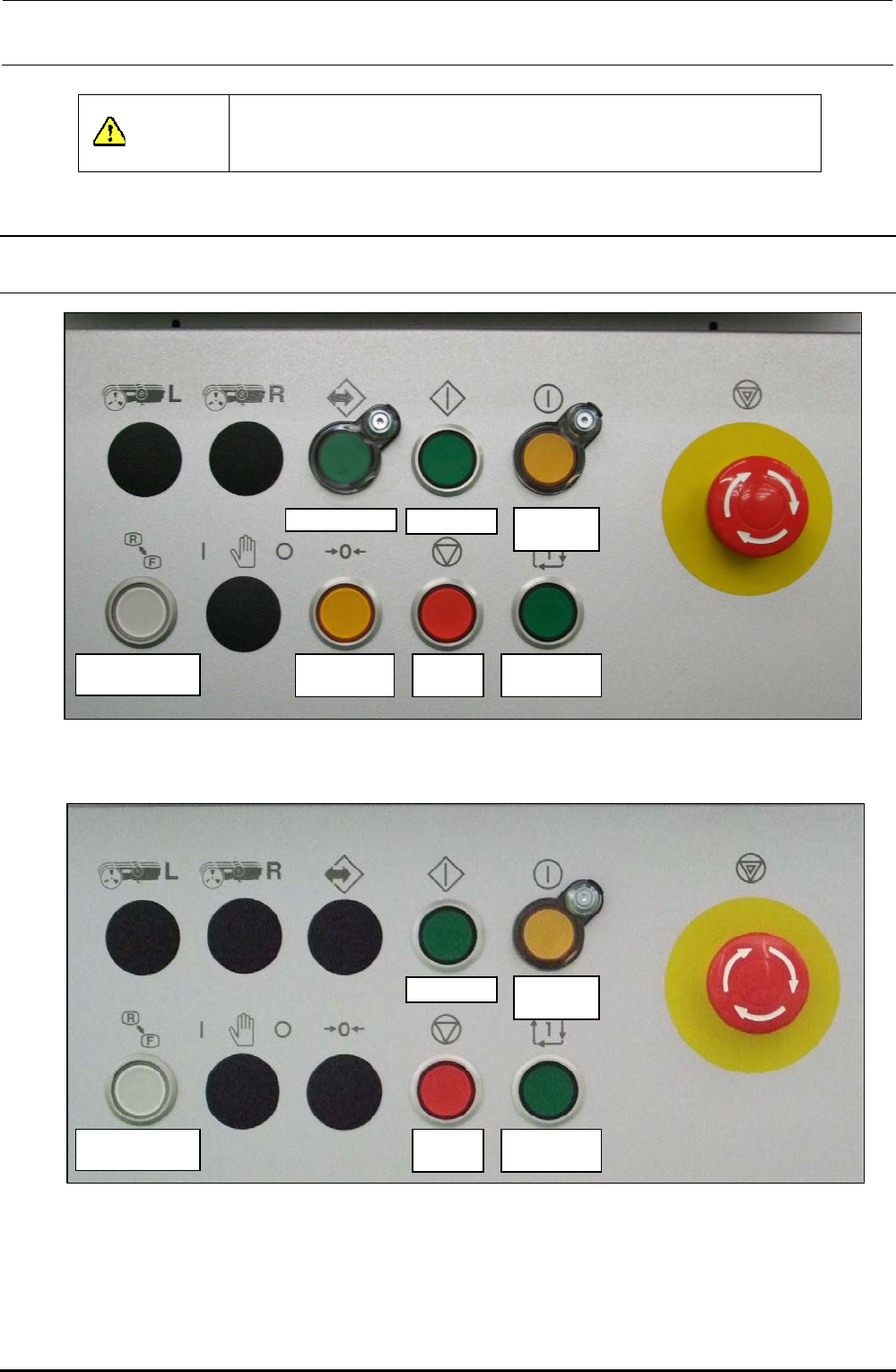
On-line switch Start switch
Servo free
switch
Keyboard setting
switch
Origin return
switch
Stop
switch
Single cycle
switch
Figure 10-1-1 Switch Names on Front Operation Panel
Start switch
Servo free
switch
Keyboard setting
switch
Stop
switch
Single cycle
switch
Figure 10-1-2 Switch Names on Rear Operation Panel
Rev. 1.00
FX-3R Maintenance Guide
10-2
1) Detach the switch panels from the front and rear sides. (Front, screws at 2 locations, Inside of
cover, screws at 2 locations)
2) Detach the operation board.
3) To detach the switch, remove the root part (mounting nut) of the switch from the back of the
cover and pull out the case from the cover surface.
4) Reassemble the components in the reverse order of disassembly.
Turn.
Turn.
Mounting
nut
Edge
Stop metal fitting
Groove
Panel
Pull out.
Case
Figure 10-1-4 Back of Cover Figure 10-1-5 Detaching the Switch
∗ The list of replacement parts is described in section 13-9-3.
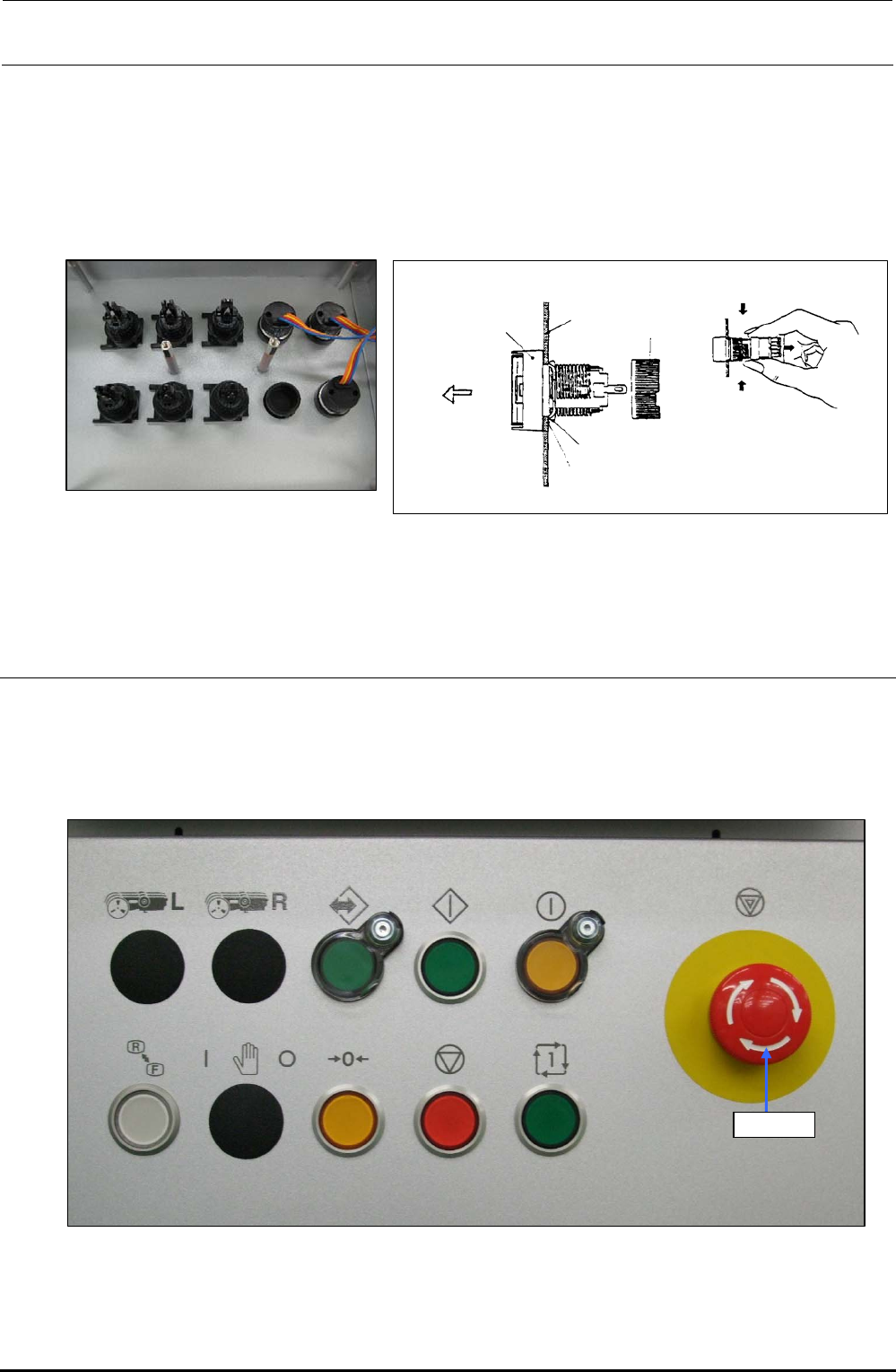
10-2. Replacing the EMERGENCY STOP Switch
1) Remove the knobs c on the front and rear to detach the EMERGENCY STOP switch from the
back of the cover.
2) Disconnect the cables from the rear of the switch with a screwdriver to replace the switch with a
new one.
Knob c
Figure 10-2-1 Operation Panel (Front Side)
∗ The list of replacement parts is described in section 13-9-3.
Rev. 1.00