JUKI FX-3R MAINTENANCE GUIDE.pdf - 第225页
FX-3R Maintenance Guide 13-56 The above Photo shows the back side of the operation panel of the machine with the ST specifications. When assembling the operation switches (1) and (2), make the conv ex part of the switch …
FX-3R Maintenance Guide
13-55
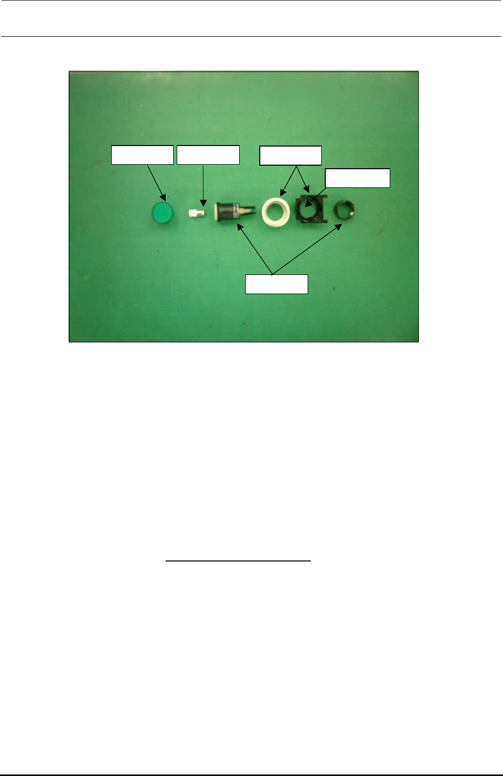
2) Mounting switches
Lenses
Green, red, yellow
Switch actuator
Bezel
With/without cover
+24V LEDs
Green, orange
Projection shall
face leftward.
<Procedure>
(1) ONLINE, ORIGIN, START, STOP, SERVOFREE, CYCLE switches
• Parts used
Lens for flat (HA005520010, HA00552001A, HA00552001B)
LED (HA005340070, HA00534007A)
Bezel (HA005520030, HA00534004A)
Switch actuator (HA005340020)
<Procedure>
c Fit the bezel (black) into the cover panel.
The bezel has a projection to stop rotation.
Attach the bezel so that
the projection faces to the left when viewed from the front.
d Insert the LED into the switch actuator, and fit the actuator over the projection of the bezel
carefully. There is a nut to be used to fix the bezel, so remove it.
e Insert the bezel (silver) from the back of the panel and secure it with the fixing nut.
f Finally, fit the lens for flat into the switch actuator firmly.
∗ References are shown on the following page.
Rev. 1.00
FX-3R Maintenance Guide
13-56
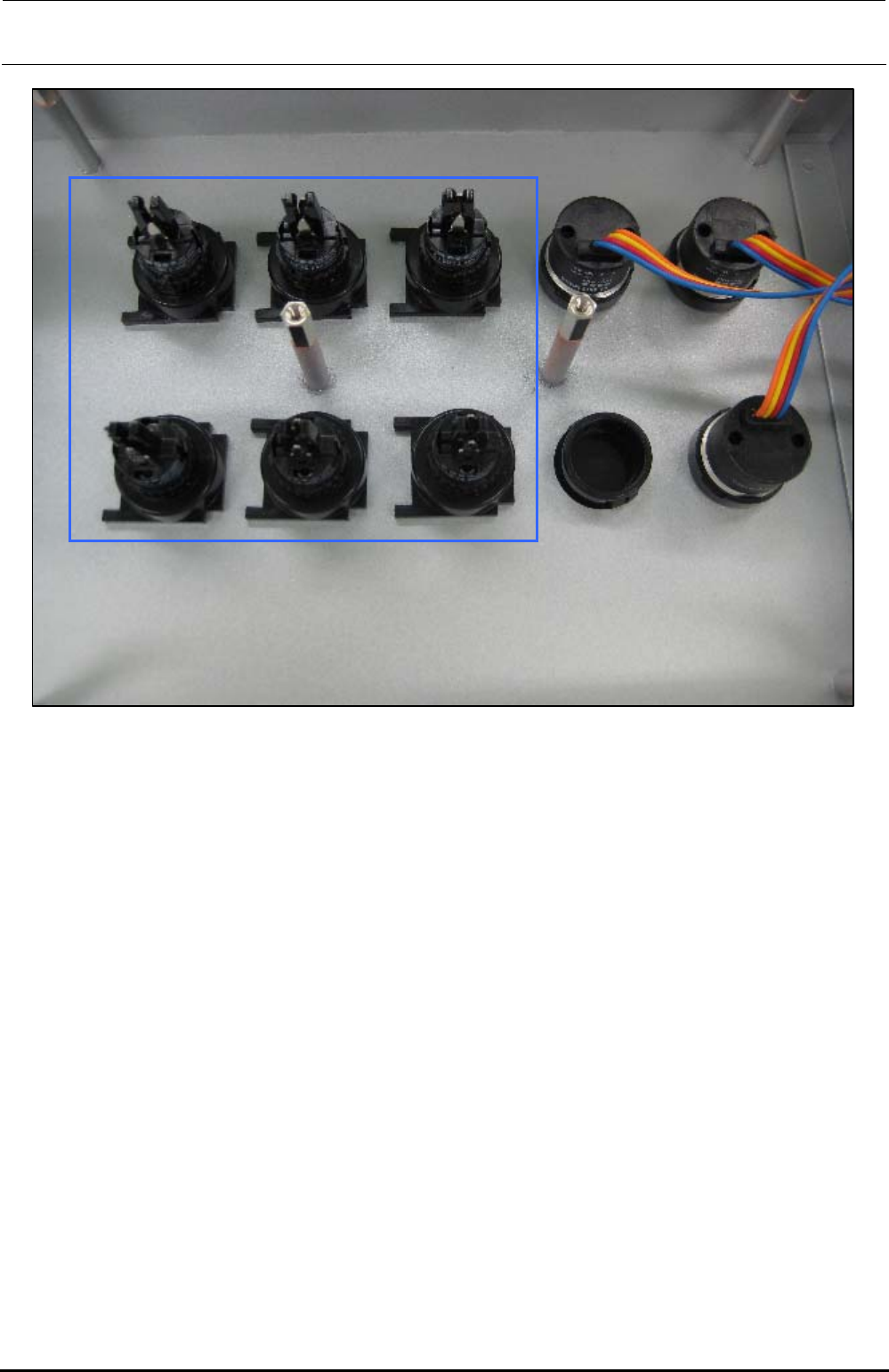
The above Photo shows the back side of the operation panel of the machine with the ST
specifications. When assembling the operation switches (1) and (2), make the convex part of the
switch faced rightward when viewed from the back side of the operation panel as shown in the
Photo.
∗ The Photo shows the back side of the operation panel on the front of the machine with the ST
specifications. Regardless of the front and rear operation panels for the ST and EN
specifications, and bezel shapes (pushbutton type and key type, etc.), always make the convex
part of the switch faced rightward when viewed from the back side of the operation panel.
Rev. 1.00
FX-3R Maintenance Guide
13-57
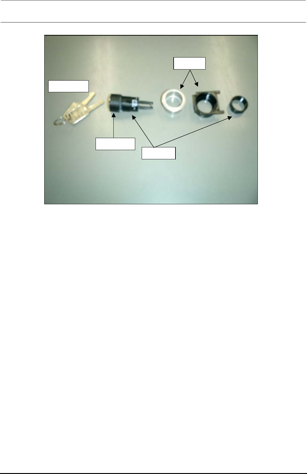
(2) Maintenance key switch
Switch key supplied
with the machine
Bezel for key
switch
Bezel
Key switch
actuator
• Parts used
Key cover (HA00535003A), Key switch actuator (HA005350020), Bezel (HA005520020)
<Assembly procedure>
c Fit the bezel (black) into the cover panel.
d Push the key cover into the key switch actuator until a click is heard.
e Insert the actuator (assembled at 3) into the black bezel, insert the bezel (silver) from the
back of the panel and secure it with the fixing nut.
(3) CONSOLE CHANGE
• Parts used
Use the CONSOLE SW ASM (40048036).
Bezel (white) with a lens: bezel (HA005530010), lens (HA00553002A); to be used for the
CONSOLE CHANGE.
<Assembly procedure>
c Remove the fixing nut of the bezel and fit the bezel. Then tighten the fixing nut.
d Finally, fit the switch element (with a cable) from the back of the panel. Direction of the
switch element is not important. It can be assembled in either direction.
Rev. 1.00