JUKI FX-3R MAINTENANCE GUIDE.pdf - 第74页
FX-3R Maintenance Guide 5-21 Rev. 1.00 5-14. Auto PWB Width Adjustment 5-14-1. Replacing the AWC Motor 1) Disconnect the connectors of the motor relay cable. 2) Loosen the set screws e on the motor bracket d to detach th…

FX-3R Maintenance Guide
5-20
Rev. 1.00
[List of Replacement Parts]
Table 5-13-2 Reference for PWB Positioning Hole
Part No. Part name Part No. Part name
1∗
1
PV150209000
5-PORT SOLENOID VALVE
7∗
1
PV150209000
5-PORT SOLENOID VALVE
2 PV150209300
5-PORT SOLENOID VALVE
8 PV150209300
5-PORT SOLENOID VALVE
3 PV150209300
5-PORT SOLENOID VALVE
9 PV150209300
5-PORT SOLENOID VALVE
4 40047772 WAIT-L SENSOR ASM 10 40047775 WAIT-R SENSOR ASM
5 40047774 STOP-L SENSOR ASM 11 40047777 STOP-R SENSOR ASM
6 40047773 COUT-L SENSOR ASM 12 40047776 COUT-R SENSOR ASM
∗
1
In the case of EN type, a solenoid valve (PV150209000) is provided in addition to those
provided as the standard specifications.
∗
2
In the figure, BU(EN), SHAPE Y, and STOPPER are solenoid valves; WAIT, STOP, and
C-OUT are sensor amplifiers.
FX-3R Maintenance Guide
5-21
Rev. 1.00
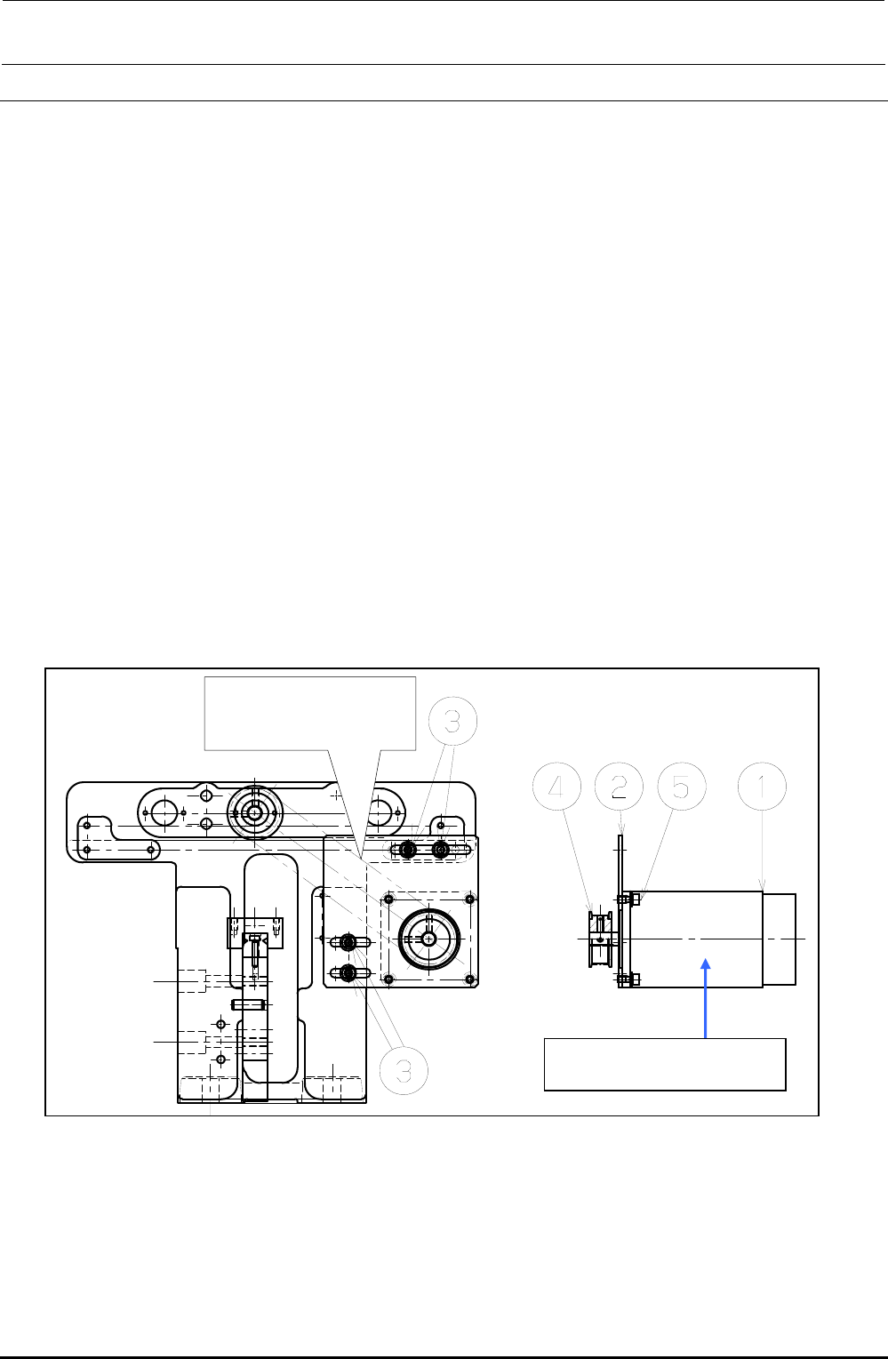
5-14. Auto PWB Width Adjustment
5-14-1. Replacing the AWC Motor
1) Disconnect the connectors of the motor relay cable.
2) Loosen the set screws e on the motor bracket d to detach the drive belt from the motor pulley
f.
3) Loosen the motor set screws g to detach the motor c.
4) Detach the motor pulley f from the motor.
5) Reassemble the components in the reverse order of steps 1) to 4). At this time, assemble the
components so that the end face of the motor shaft is aligned with the end face of the pulley f.
6) Adjust the tension of the drive belt.
• Belt tension adjustment procedure
Measure the tension at the center of the belt (see the Figure below) with UNITTA's belt tension
meter.
c Values to be input to tension meter Weight: 002.5
Width: 009.0
Span: 0133
d Adjustment value 25± 2.5N⋅m
Figure 5-14-1-1 AWC Motor
Measure the belt tension
at this position with the
tension meter.
c E94347290A0
AWC Motor Assembly
FX-3R Maintenance Guide
5-22
Rev. 1.00
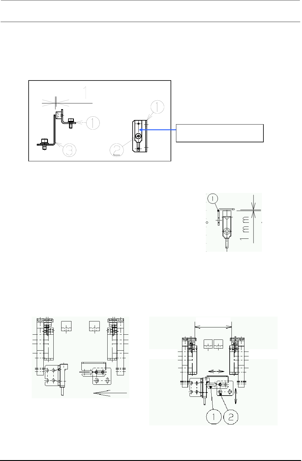
d Move the sensor dog (c) leftward until the
sensor LED goes on. Then bring the dog
closer another 1mm.
Transport
width 50mm
"Reference side"
"Driven side"
5-14-2. Replacing the AWC Origin Sensor
1) Loosen the screw d. Detach the AWC origin sensor from the AWC origin sensor bracket c and
replace it with a new one.
2) Assemble the AWC origin sensor so that the clearance between the AWC sensor dog e and
the AWC origin sensor becomes 1 mm.
Figure 5-14-2-1 AWC Origin Sensor
5-14-3. Replacing the Transport Stopper Interference Sensor
1) Adjust the clearance between the sensor dog and the transport stopper interference sensor to
1 mm.
2) Sensor dog assembling position
Narrow the transport width and gradually bring the sensor dog nearer to the transport stopper
interference sensor. After the sensor is turned on (i.e. the LED goes on), move the dog another
1mm in the direction indicated by the arrow, and fix it there.
Figure 5-14-3-1 Sensor Dog Clearance
c While the power is ON, manually
narrow the transport width while
holding down the EMERGENCY
STOP button.
40002120
AWC Origin Sensor Assembly