JUKI FX-3R MAINTENANCE GUIDE.pdf - 第32页
FX-3R Maintenance Guide 2-14 2-7. Readjustment After Replacement of Head Unit Table 2-7-1 List of Readjustment It ems After Replacement of Head Unit Laser ID No. setup Laser offset Head offset Component speed measurement…
FX-3R Maintenance Guide
2-13
2-6. Replacing the Z-Slide Shaft
When the Z-slide shaft has been replaced, it is necessary to input the MS parameters related to the
θ-axis and Z-axis home position adjustment, Z-axis height, and laser again.
(For details about input items, see section 2-7.)
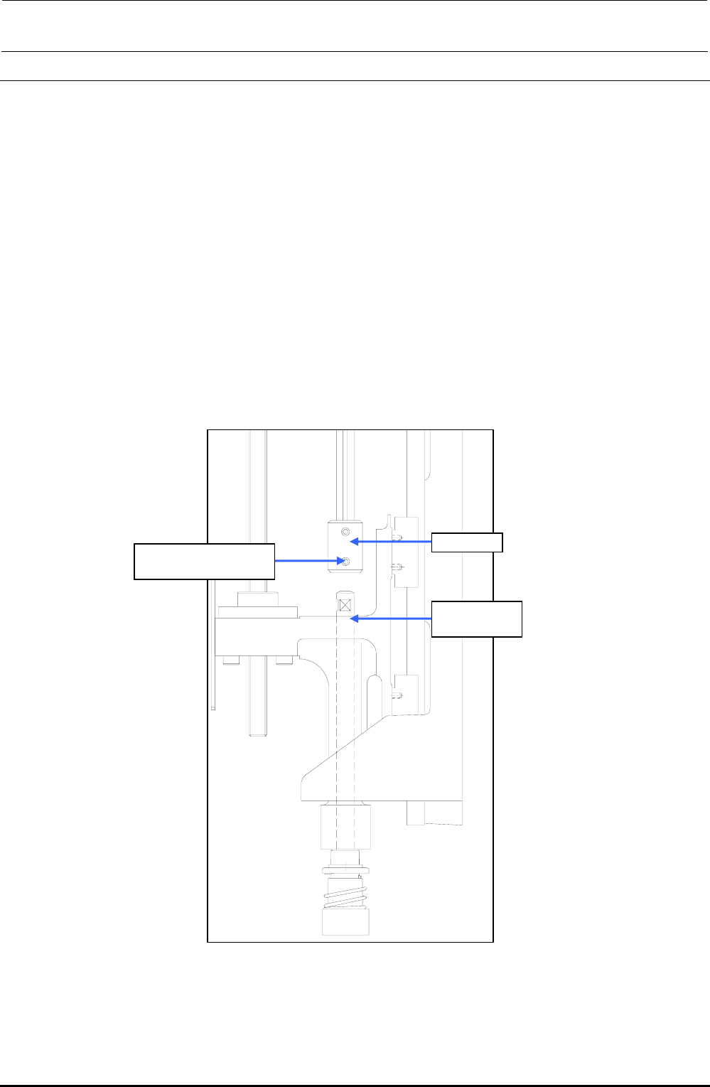
(1) Remove the hollow set screw c (×1) from the lower portion of the coupling.
(2) Detach the Z-slide shaft from the Z-slide bracket.
(3) Reassemble the components in the reverse order of disassembly.
∗ Secure the coupling with it kept pushed-in and make sure that any vertical play does not
exist on the slide shaft.
∗ When tightening the set screws of the coupling, align the flat part of the slide shaft with
the orientation of the coupling set screw. Tighten the set screw with a tightening torque of
0.5 N・m.
Rev. 1.00
c SM8030312TP
Set screw M3 L=3
Coupling
40044586
Z-slide Shaft
Figure 2-6-1 Z-slide Shaft
FX-3R Maintenance Guide
2-14
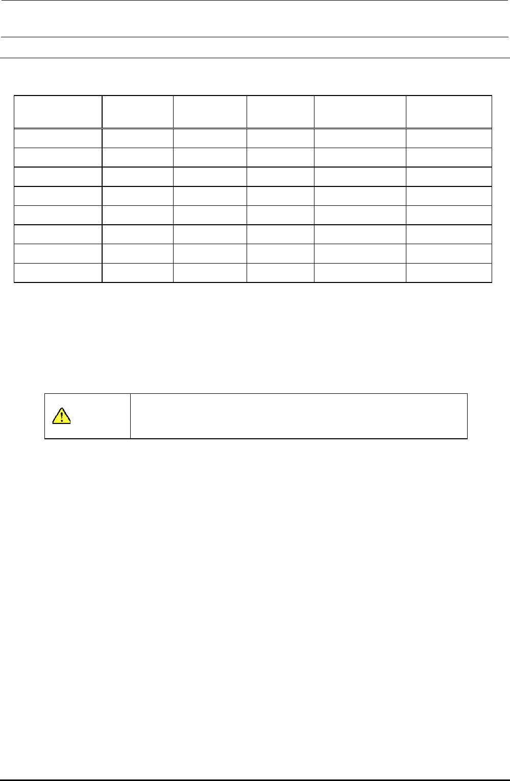
2-7. Readjustment After Replacement of Head Unit
Table 2-7-1 List of Readjustment Items After Replacement of Head Unit
Laser ID No.
setup
Laser offset Head offset
Component speed
measurement
Mounting general
offset
Head unit assembly { { {
Z-motor {
θ-motor
{ {
Z-sensor {
LNC60 { { { { {
Timing belt Z {
Timing belt θ
{ {
Z-slide shaft { { {
The MS parameters must be input from the left in order.
When inputting a laser offset after the head unit assembly, Z-motor, and/or timing belt Z have been
replaced, obtain the laser offset again after the height of the top surface of the laser offset board has
been set to “0”. According to the offset value before replacement, the offset cannot be obtained
correctly or it cannot be obtained automatically.
CAUTION
To prevent any personal injury, do not put your hand inside the
machine or your face or head close to the machine during operation
of the touch panel and/or HOD.
Rev. 1.00

FX-3R Maintenance Guide
3-1
DANGER
To prevent any trouble caused by accidental machine start, always
shut-down the power before starting the maintenance and
adjustment work.
The XY-axis uses a very strong magnet.
• Do not put any metallic object close to the magnet surface. Once the
magnet attracts a metallic object, this object cannot be removed due to
strong magnetic force.
• Before starting the maintenance work, take off precision portable devices,
such as a wrist watch from your body.
• Do not allow personnel who uses a precision medical device, such as an
artificial cardiac pacemaker, etc to carry out the maintenance work.
[3] PARTS AROUND THE HEAD
3-1. Replacing the Solenoid Valves
Before replacing the solenoid valves, always shut-down the main compressed air.
1) Remove the SEMS cap bolts c (×2) and SEMS cap bolts d (×2) to detach the SV cover and
cable guide.
2) Remove the SEMS cap bolts e (×2), and disconnect the cables and air tubes to detach the
solenoid valve main unit.
3) Remove the round head screws f (×2) to detach each solenoid valve. (Great care should be
taken so that the gasket on the back of the solenoid valve is not lost.)
4) Reassemble the parts and components in the reverse order of disassembly.
5) After the solenoid valves have been replaced, check the solenoid valves through the head
vacuum and the blow ON/OFF of the manual control.
∗ Round head screws f (2 pcs.) and gasket (1 pc.) are accessory parts supplied with each
solenoid valve.
Rev. 1.00