JUKI FX-3R MAINTENANCE GUIDE.pdf - 第190页
FX-3R Maintenance Guide 13-21 13-4-6. IP-X5 Board Assembly (40047528) [Functions] This IP-X5 board is an image processing board that processes image data, such as board mark and IC mark captured by the OCC camera to calc…
FX-3R Maintenance Guide
13-20
13-4-5. ETHER-MAIN Board (40048066)
[Functions]
This ETHER-MAIN board is a host board used to communicate with the ETHER-SLAVE board
through the Ethernet.
The board is connected to the Compact PCI (hereafter referred to as “cPCI”) bus so as to
access each peripheral I/O from the CPU board. Additionally, the MS parameter backup data is
saved into the FLASH ROM.
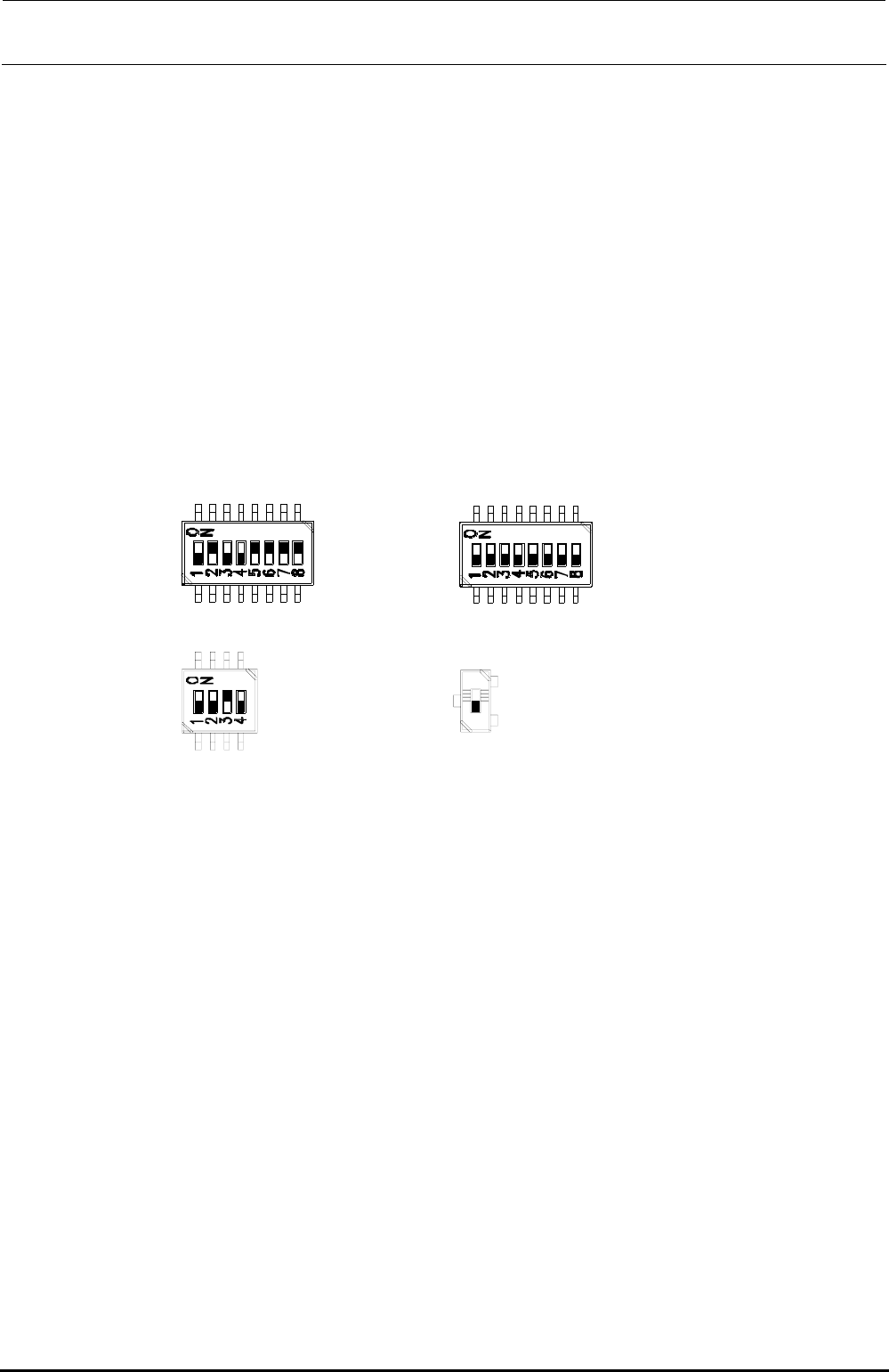
[DIP switch settings]
The DIP switches have been set properly at the delivery of the machine. When setting the board
in the control unit, check the DIP switch settings. ( portions show the switch positions.)
SW2-1 :OFF
SW2-2 :ON
SW2-3 :OFF
SW2-4 :OFF
SW2-5 :ON
SW2-6 :ON
SW2-7 :ON
SW2-8 :ON
SW4-1 :OFF
SW4-2 :OFF
SW4-3 :OFF
SW4-4 :OFF
SW4-5 :OFF
SW4-6 :OFF
SW4-7 :OFF
SW4-8 :OFF
SW1-1 :OFF
SW1-2 :OFF
SW1-3 :ON
SW1-4 :OFF
SW5:OFF
Note) SW5 is not mounted
on the board
(40048066).
Figure 13-4-5-1 DIP switches on ETHER-MAIN Board Assembly
[Meaning of LED]
7-segment LED: Shows the operation status of this board.
RUN LED: Lights up when the power is supplied.
EN1: Shows Link/Act of EN1. EN1 → Left station
EN2: Shows Link/Act of EN2. EN2 → Right station
EN3: Shows Link/Act of EN3. EN3 → XY-RELAY board – BASE CARRY board –
FEEDER board
EN4: Shows Link/Act of EN4.
[Adjustment items after replacement]
After that, follow the steps below to update the FLASH memory.
c Select [Options] and [Change User Group], and then select [Serviceman].
d Select [Maintenance] and [MS Parameter Setup].
e Select [Upgrade] and [Ether Main].
f Clicking [Exec.] will start the upgrading process.
Rev. 1.00
FX-3R Maintenance Guide
13-21
13-4-6. IP-X5 Board Assembly (40047528)
[Functions]
This IP-X5 board is an image processing board that processes image data, such as board mark
and IC mark captured by the OCC camera to calculate values necessary for correction of the
board position and/or part position.
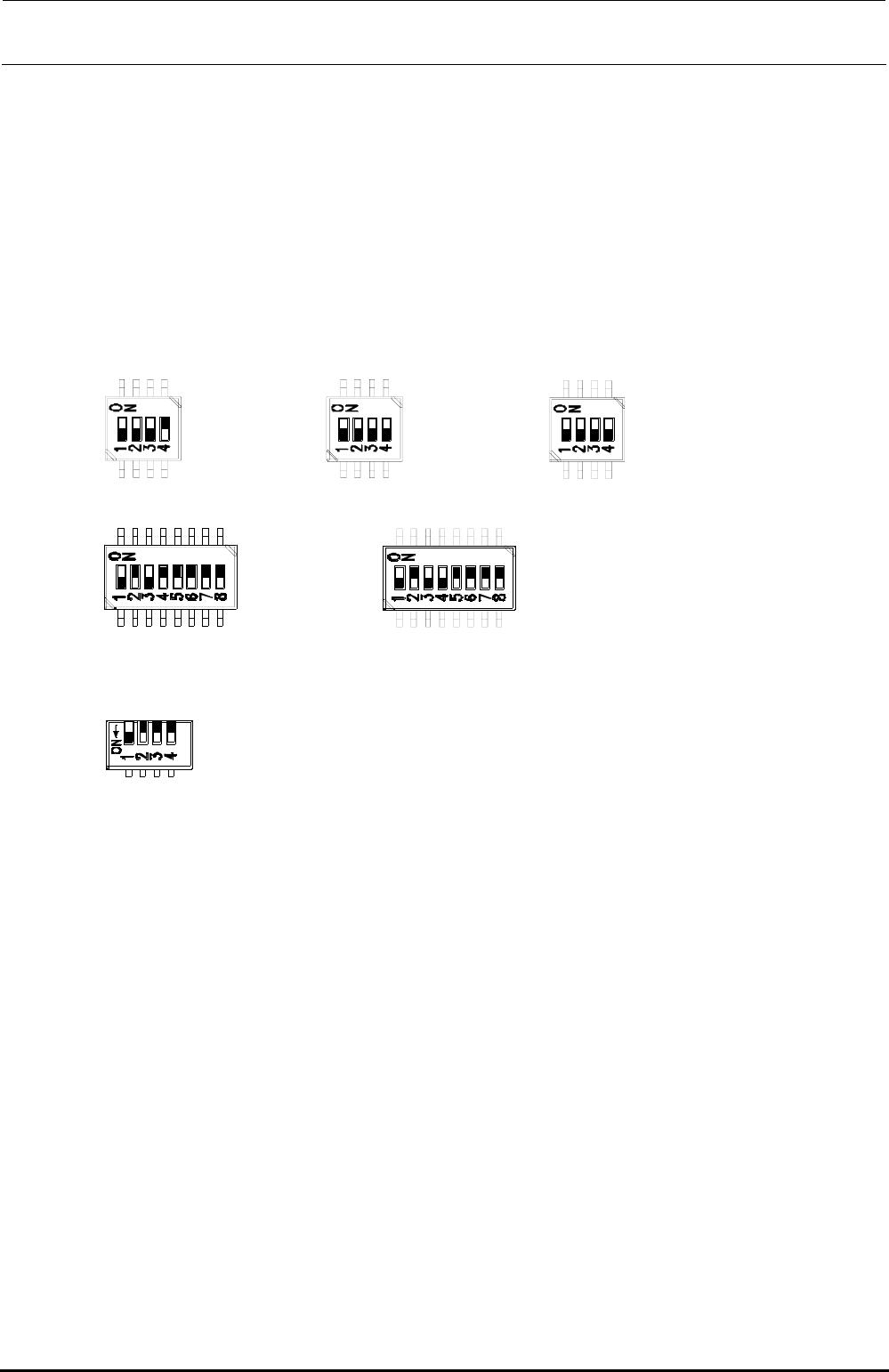
[DIP switch settings]
The DIP switches have been set properly at the delivery of the machine. When setting the board
in the control unit, check the DIP switch settings. ( portions show the switch positions.)
SW3-1 :OFF
SW3-2 :OFF
SW3-3 :OFF
SW3-4 :ON
SW6-1 :OFF
SW6-2 :OFF
SW6-3 :OFF
SW6-4 :OFF
SW8-1 :OFF
SW8-2 :OFF
SW8-3 :OFF
SW8-4 :OFF
SW4-1 :OFF
SW4-2 :ON
SW4-3 :OFF
SW4-4 :ON
SW4-5 :ON
SW4-6 :ON
SW4-7 :ON
SW4-8 :ON
SW5-1 :OFF
SW5-2 :ON
SW5-3 :OFF
SW5-4 :OFF
SW5-5 :ON
SW5-6 :ON
SW5-7 :ON
SW5-8 :ON
SW7-1 :OFF
SW7-2 :OFF
SW7-3 :OFF
SW7-4 :OFF
Figure 13-4-6-1 DIP switches on IP-X5 Board Assembly
∗ SW7 is a piano type switch, which is operated from the front panel.
[Front panel switches] ∗ Basically, do not operate these switches.
RESET SW: Resets this board.
ABORT SW: Issues NMI to the CPU.
DIP switch: Changes the settings of the board.
[Adjustment items after replacement]
After that, follow the steps below to update the FLASH memory.
c Select [Options] and [Change User Group], and then select [Serviceman].
d Select [Maintenance] and [MS Parameter Setup].
e Select [Upgrade] and [Display].
f Clicking [Exec.] will start the upgrading process.
Rev. 1.00

FX-3R Maintenance Guide
13-22
13-4-7. MOUSE/KEYBOARD Selector (40003281)
[Functions]
This MOUSE/KEYBOARD selector is intended to switch between the keyboard and mouse
console.
[DIP switch settings]
The DIP switches have been set properly at the delivery of the machine. When setting the board
in the control unit, check the DIP switch settings. ( portions show the switch positions.)
Figure 13-4-7-1 MOUSE/KEYBOARD SELECTOR DIP SW
SW-1 :ON
SW-2 :OFF
SW-3 :OFF
SW-4 :OFF
[Meaning of LED]
There are no LEDs on the MOUSE/KEYBOARD selector.
[Adjustment items after replacement]
There are no particular adjustment items.
Rev. 1.00