JUKI FX-3R MAINTENANCE GUIDE.pdf - 第229页
FX-3R Maintenance Guide 13-60 Rev . 1.00 [Meaning of LED] Part No. 40047558 No. Color Meaning Status LD1 Orange +3.3V power supply Normal: Lit LD2 Orange + 3.3V power supply for Ether Slave Normal: Lit LD3 Orange +5V pow…
FX-3R Maintenance Guide
13-59
13-11. Other Boards
13-11-1. XY-RELAY Board (40047558)
[Functions]
This XY-RELAY board relays the signals coming from the limit sensor and emergency stop
switch of each axis to input them to the position board, etc.
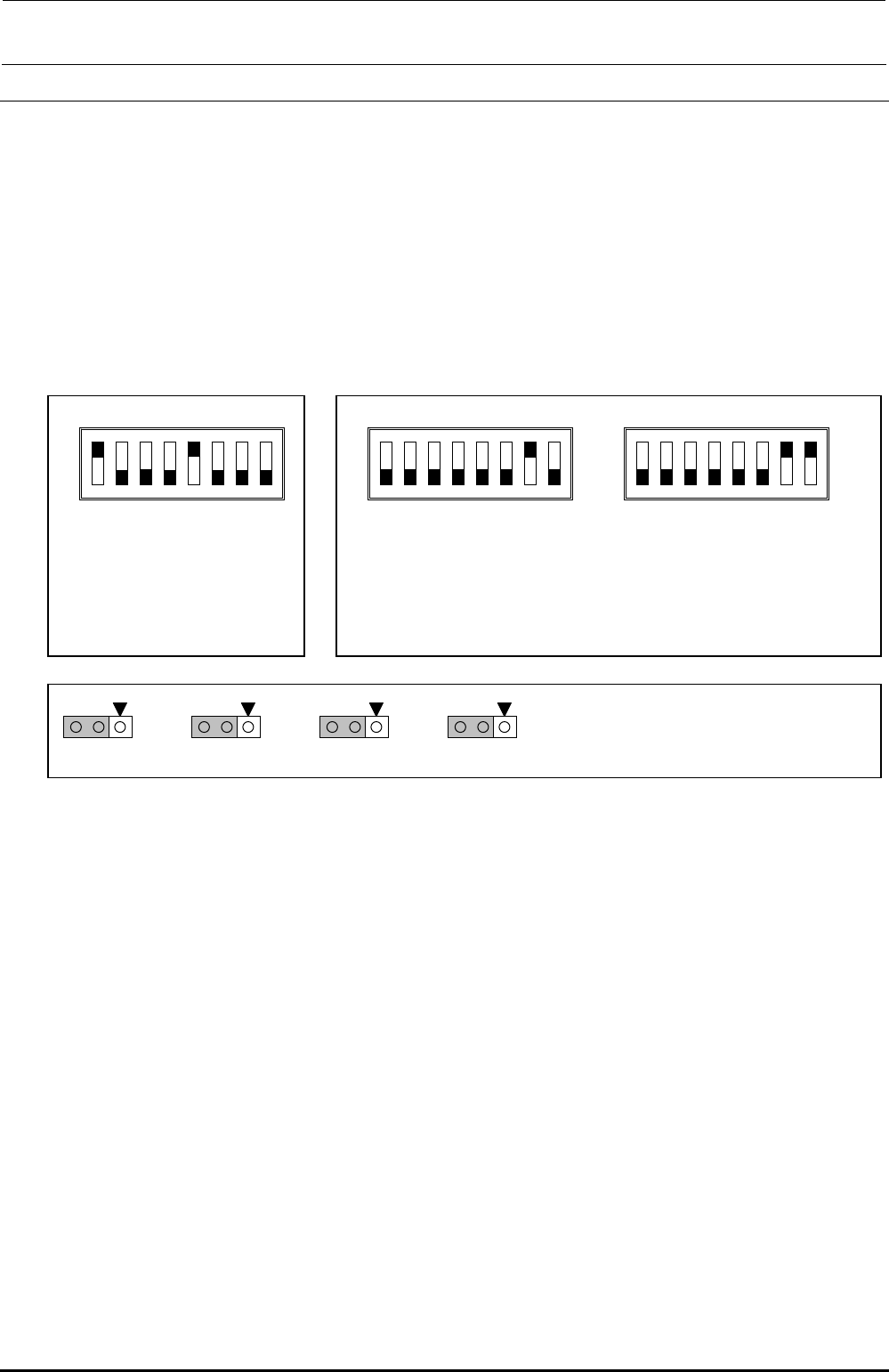
[Jumper switch settings]
portion shows the switch set position and receptacle mounting position.
Rev. 1.00
O
SW3
O
1
2
3
4
5
6
7
8
SW2
O
N
O
N
SW 2 [4..1]: Board function Rev.
SW 2 [8..5]: Board pattern Rev.
This switch has been set properly
before shipment from the factory.
Therefore, do not change this
switch setting. The above Figure
shows just an example.
O
SW3
O
N
[ST specifications: Setting
before shi
p
ment from factor
y]
[EN specifications]
SW3 to 8 are intended to set the power monitor signal valid or invalid, which
is used only for the machines with the EN specifications. Turn ON these
switches for the machines with the EN specifications.
W
5
1
3
W
6
1
3
W
7
1
3
W
8
1
3
A
ll of other W are opened.
These jumper switches have been set properly
before shipping the board. Therefore, do not change
these jumper switches.
1
2
3
4
5
6
1
2
3
4
5
6
7
8
[Adjustment items after replacement]
There are no particular adjustment items.
FX-3R Maintenance Guide
13-60
Rev. 1.00
[Meaning of LED] Part No. 40047558
No. Color Meaning Status
LD1 Orange +3.3V power supply Normal: Lit
LD2 Orange
+3.3V power supply for Ether Slave
Normal: Lit
LD3 Orange +5V power supply Normal: Lit
LD4 Green YL (LF)_Phase A Not used: (Linear scale A-phase signal H/L: Lit/Off)
LD5 Green YL (LF)_Phase B Not used: (Linear scale B-phase signal H/L: Lit/Off)
LD6 Orange YL (LF)_Origin sensor Not used: (Origin sensor detected.: Lit)
LD7 Green YR (LF)_Phase A Not used: (Linear scale A-phase signal H/L: Lit/Off)
LD8 Green YR (LF)_Phase B Not used: (Linear scale B-phase signal H/L: Lit/Off)
LD9 Orange YR (LF)_Origin sensor Not used: (Origin sensor detected.: Lit)
LD10 Green YL (LR)_Phase A Not used: (Linear scale A-phase signal H/L: Lit/Off)
LD11 Green YL (LR)_Phase B Not used: (Linear scale B-phase signal H/L: Lit/Off)
LD12 Orange YL (LR)_Origin sensor Not used: (Origin sensor detected.: Lit)
LD13 Green YR (LR)_Phase A Not used: (Linear scale A-phase signal H/L: Lit/Off)
LD14 Green YR (LR)_Phase B Not used: (Linear scale B-phase signal H/L: Lit/Off)
LD15 Orange YR (LR)_Origin sensor Not used: (Origin sensor detected.: Lit)
LD16 Green YL (RF)_Phase A Not used: (Linear scale A-phase signal H/L: Lit/Off)
LD17 Green YL (RF)_Phase B Not used: (Linear scale B-phase signal H/L: Lit/Off)
LD18 Orange YL (RF)_Origin sensor Not used: (Origin sensor detected.: Lit)
LD19 Green YR (RF)_Phase A Not used: (Linear scale A-phase signal H/L: Lit/Off)
LD20 Green YR (RF)_Phase B Not used: (Linear scale B-phase signal H/L: Lit/Off)
LD21 Orange YR (RF)_Origin sensor Not used: (Origin sensor detected.: Lit)
LD22 Green YL (RR)_Phase A Not used: (Linear scale A-phase signal H/L: Lit/Off)
LD23 Green YL (RR)_Phase B Not used: (Linear scale B-phase signal H/L: Lit/Off)
LD24 Orange YL (RR)_Origin sensor Not used: (Origin sensor detected.: Lit)
LD25 Green YR (RR)_Phase A Not used: (Linear scale A-phase signal H/L: Lit/Off)
LD26 Green YR (RR)_Phase B Not used: (Linear scale B-phase signal H/L: Lit/Off)
LD27 Orange YR (RR)_Origin sensor Not used: (Origin sensor detected.: Lit)
LD28 Red FPGA configuration for Operation I/F Configuration completion: Lit
LD29 Red Console change-over Front valid: Lit., Rear valid: Off
LD30 Yellow
Not used
⎯
LD31 Yellow
Not used
⎯
LD32 Yellow
Not used
⎯
LD33 Yellow
Not used
⎯
LD34 Red FPGA configuration for Ether communication
Configuration completion: Lit
LD35 Blue Not used
⎯
LD36 Blue AreaEMG
Area sensor detection: Off
(However, when SW3_6 = OFF, the LED is always lit.)
LD37 Blue Axis Lim EMG
Axis Lim sensor detection: Off
(However, when SW3_7 = OFF, the LED is always lit.)
LD38 Blue PowerMonEMG (EN)
PowerMon detection: Off
(However, when SW3_8 = OFF, the LED is always lit.)
FX-3R Maintenance Guide
13-61
Rev. 1.00
13-11-2. FEEDER Board (40047560)
[Functions]
One board is arranged for each of the left and right stations, two boards in total.
c ATC open/close (WRITE) and its check sensor
d Feeder rise sensor, feeder detection sensor
e Bank up sensor is detected.
f CAL block LED is lit and vacuum is turned ON.
g Vacuum calibration sensor
h Feeder knock pin is driven.
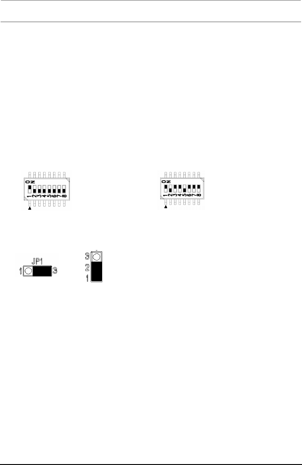
[Jumper switch settings]
portion shows the switch set position and receptacle mounting position.
DSW1 DSW2
[Adjustment items after replacement]
After that, follow the steps below to update the FLASH memory.
c Select [Options] and [Change User Group], and then select [Serviceman].
d Select [Maintenance] and [MS Parameter Setup].
e Select [Upgrade] and [Feeder].
f Clicking [Exec.] will start the upgrading process.
Jumper JP1 Jumper JP2 to 11
SW 2 [4..1]: Board function Rev.
SW 2 [8..5]: Board pattern Rev.
This switch has been set properly before shipment from
the factory. Therefore, do not change this switch setting.
The above Figure shows just an example.
No. 1: ON
No. 2 to 8: OFF