JUKI FX-3R MAINTENANCE GUIDE.pdf - 第131页
FX-3R Maintenance Guide 12-2 12-1-2. Setting Up the Touch Pa nel (TECNART, TM150-JDA03) After the LCD monitor has been replaced, it is necessary to set up the touch panel. 1) Check the [MENU] and [-] buttons on the front…
FX-3R Maintenance Guide
12-1
DANGER
To prevent any trouble caused by accidental machine start, always
shut-down the power before starting the maintenance and
adjustment work.
[12] OTHER UNITS
12-1. LCD Monitor
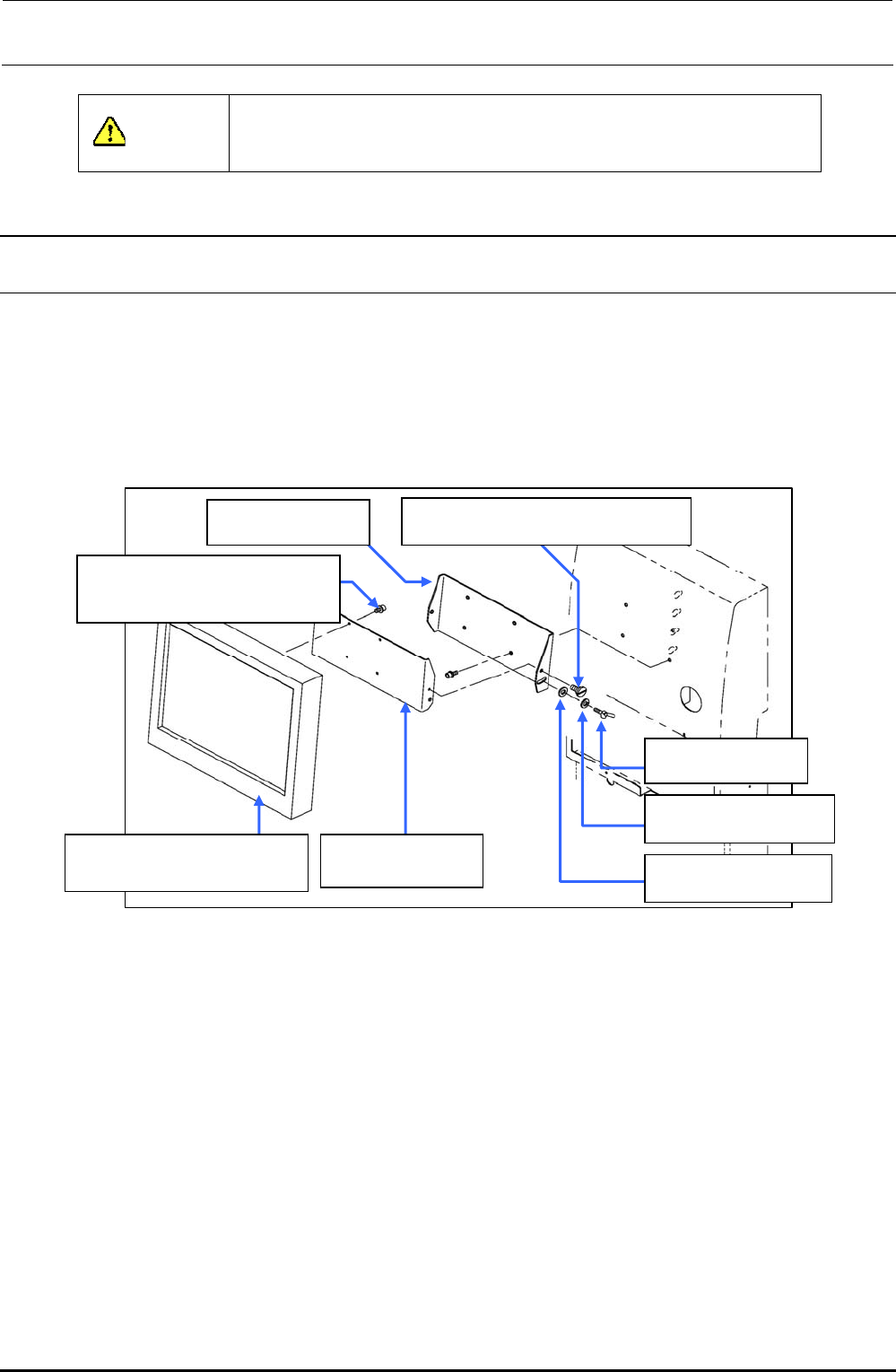
12-1-1. Replacing the LCD Monitor
1) Remove the shoulder screws and thumbscrews , and to detach the LCD bracket F
from the LCD bracket R .
2) Remove the SEMS cap bolts to detach the LCD bracket F from the LCD monitor .
3) Reassemble the components in the reverse order of disassembly.
40048083
TECNART’s LCD monitor
40047170
LCD bracket F
SD0640246SP
Shoulder screw D=6.35 H=2.4
SL6041092TN
SEMS cap bolt with washer
M4×10
WP0641601SC
Plain washer M6
WS0610002KN
Spring washer M6
16187007
Thumbscrew
40047171
LCD bracket R
Figure 12-1-1-1 LCD Monitor
Rev. 1.00
FX-3R Maintenance Guide
12-2
12-1-2. Setting Up the Touch Panel (TECNART, TM150-JDA03)
After the LCD monitor has been replaced, it is necessary to set up the touch panel.
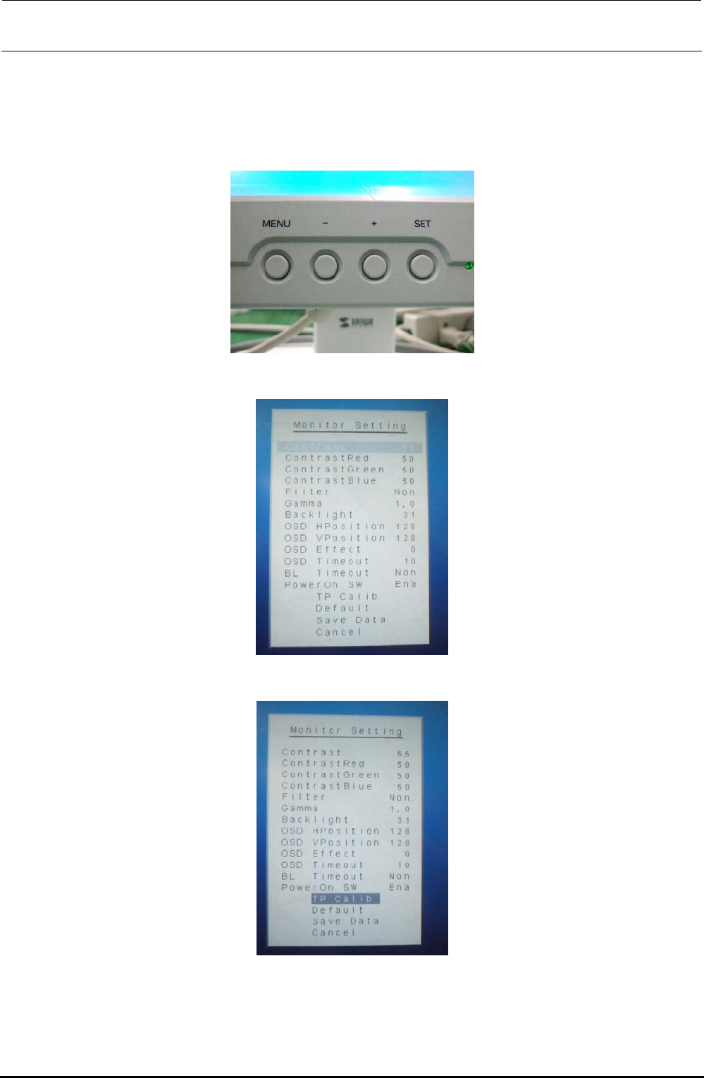
1) Check the [MENU] and [-] buttons on the front of the LCD monitor.
2) Press the [MENU] button to display the “Monitor Setting” screen.
3) Press the [-] button to select [TP Calib] on the “Monitor Setting” screen.
Rev. 1.00
FX-3R Maintenance Guide
12-3
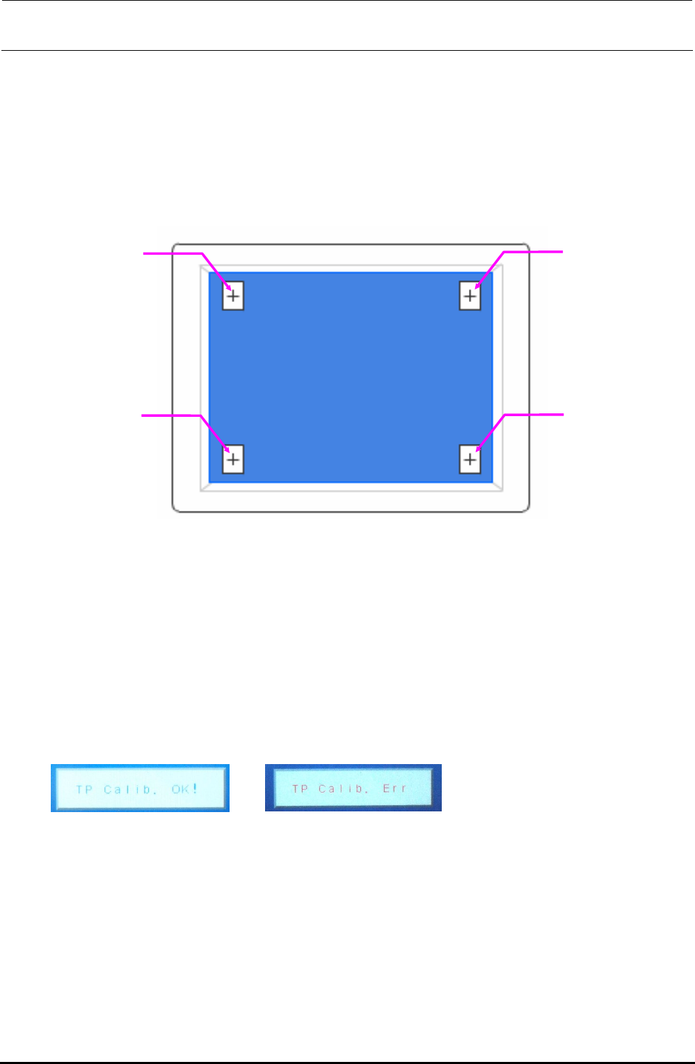
4) Next, press the [MENU] button. [+] is shown at the lower right corner of the screen. Touch its
center portion.
5) [+] is shown at the lower left corner of the screen. Touch its center portion.
6) [+] is shown at the upper right corner of the screen. Touch its center portion.
7) [+] is shown at the upper left corner of the screen. Touch its center portion.
Touch positions on monitor screen
CAUTION
To adjust the touch panel, use finger or touch pen with a round tip.
Do not use any propelling pencil or sharp object. Always press the center portion of the
calibration point. The target is 1 mm or less.
If a position other than the mark is pressed, ERR appears after approx. 5 sec. have elapsed. At
this time, restart the adjustment from work step No. 1.
8) Finally, when “TP Calib. OK!” is shown, this means that the setting has been completed
successfully.
Completed successfully. Err display
CAUTION
If “TP Calib. Err” appears during operation or at the end of the operation, restart the adjustment
from work step No. 1.
Rev. 1.00