KE2010.Instruction Manual.Ver.2.01,Rev.08.pdf - 第296页
4 – 189 4.12.1.2 Auto convey or This comm and adjusts t he width of the PW B transport rails. W hen y ou select this com mand, t he following dialog box appears on the screen. Figure 4.12.1.2. 1 Automatic conv eyor width…
4 – 188
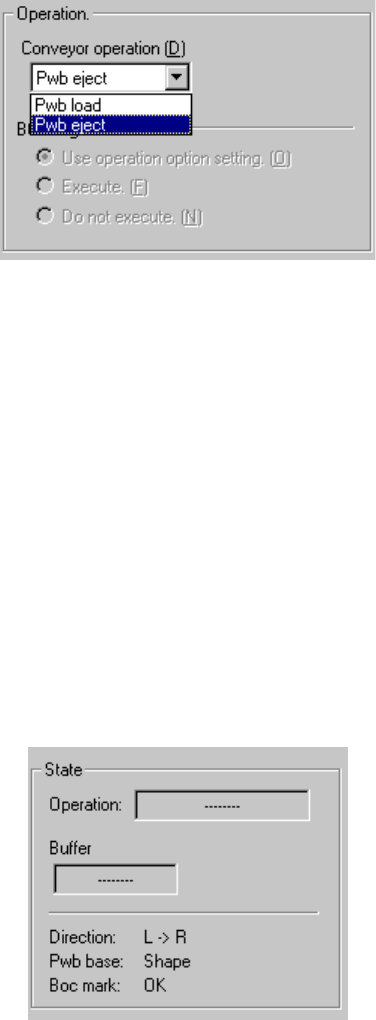
1) Operation
① Loading/Ejecting a PWB
Select whether to load or eject a PWB on the “Conveyor operation” list.
② BOC alignment
Select whether to perform BOC alignment operation after loading a PWB.
When you select the radio button “Follows the operation option.”, the setting
of the teaching item provided as the Operation Options is applied to the BOC
alignment operation.
2) State
The current PWB transport operation settings and status are displayed
sequentially.
To start transporting a PWB, press the <Start> button (or click the <Execution>
button). To finish transporting a PWB, click the <Exit> button. To abort operation
while a PWB is being transported for some reason, press the <Stop> button.
4 – 189
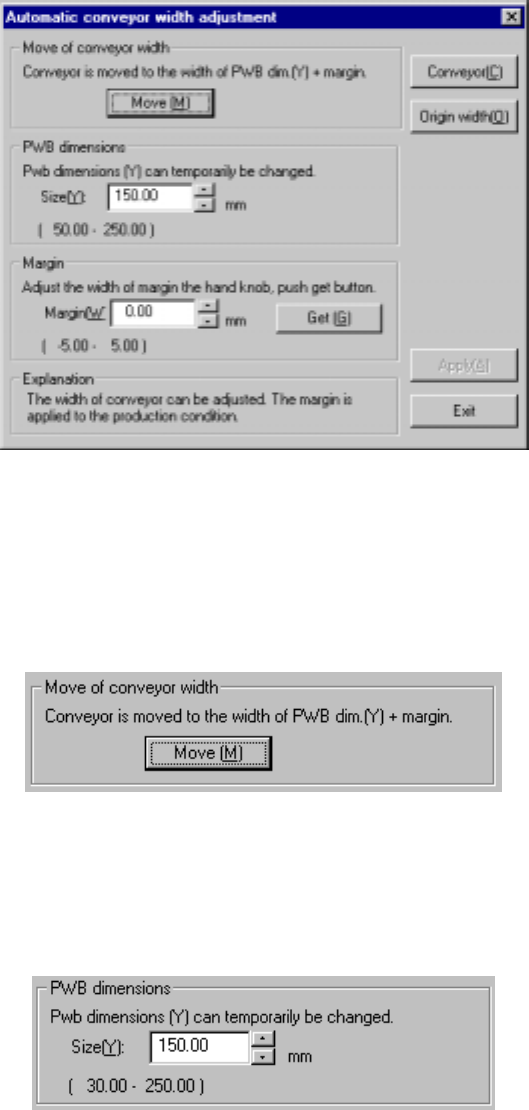
4.12.1.2 Auto conveyor
This command adjusts the width of the PWB transport rails.
When you select this command, the following dialog box appears on the screen.
Figure 4.12.1.2.1 Automatic conveyor width adjustment dialog box
1) Move of conveyor width
The <Move> button changes the width of the PWB transport rails to the width:
PWB dimension (Y) + the margin. The values of the following items are applied to
the actual width during transportation of a PWB.
2) PWB dimensions
Use the spin button or enter a number from a keyboard to set the dimensions of a
PWB. As the default setting, the PWB dimension (Y) specified in PWB data is
entered here.
4 – 190
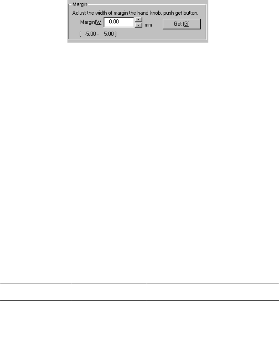
3) Margin
① Margin (W)
Use the spin button or enter a number from a keyboard to set the margin
between a PWB and the PWB transport rails.
② <Get> button
This button subtracts the PWB dimension (Y) from the current width of the
PWB transport rails, and sets the result as the margin. Use the knob located
on the front of the main unit to adjust the PWB transport rails width before
clicking this button.
4) <Conveyor> button
This button invokes the Conveyor dialog box.
5) Origin width
This button zeroes the automatic PWB width adjustment device.
6) <Apply> button
This button applies the value set as the margin to the production conditions.
To quit this dialog box, click the <Exit> button.
4.12.2 Measurement
This command allows a component to be attached on actually to measure it with each
hardware device, then loads the measured result to a production program.
4.12.2.1 Measurement mode
Two types of modes are provided for measurement operation: “Continuous
Measurement” and “Single Measurement”. To switch mode, select the
corresponding command.
The command and its corresponding measurement mode are shown in Table below:
Table 4.12.2.1 Measurement mode and its corresponding menu command
Command on the
Measurement sub-menu
Measurement mode Description
Current component Single Measurement Measures a component displayed on the
Component form screen.
All component Continuous Measurement Measures all components/components which
satisfy the conditions specified in a production
program. In Single Measurement mode, you can
measure a component which failed to be measured
for some reason individually.