00191099-01.pdf - 第41页
Component B ar-Code Sc anner (Optional) Retrofitting Instructions SIPLACE 80 / S-23 (HM) / HS-50 Issue 06/00 2.7 Component Bar-Code S canner on S-20/F4/F4-6/F5 (HM) and S- 23 (HM) 41 &RPSRQHQW %DU&RGH 6FDQ…
Retrofitting Instructions SIPLACE 80 / S-23 (HM) / HS-50 Component Bar-Code Scanner (Optional)
2.6 Requirements Issue 06/00
40
5HTXLUHPHQW V
There are no additional hardware and software requirements for ANY of the placement machines
mentioned in these instructions aside from the required exchange of the keyboard on the
SIPLACE 80 S-15 / F3. However, this keyboard is included in the retrofit kit.
For all machines SIPLACE 80 und S-23 (HM) we recommend that you upgrade the software for
the line computer and station computer to the current version while carrying out this retrofitting.
Please refer to the Software Approval List for the Item no. of the current software.

Component Bar-Code Scanner (Optional) Retrofitting Instructions SIPLACE 80 / S-23 (HM) / HS-50
Issue 06/00 2.7 Component Bar-Code Scanner on S-20/F4/F4-6/F5 (HM) and S-23 (HM)
41
&RPSRQHQW%DU&RGH6FDQQHURQ6)))
+0DQG6+0
+DUGZDUH,QVWD OODWLRQIRU3&&DUULHUVDQG
Å Turn the machine OFF and isolate it from the mains (details -> see DANGER text in Section
2.2).
Å Leave the safety hoods closed.
Å Unplug the plug-and-socket connections on the back of the station monitor.
Å Lift the station monitor off the carrier.
Å Attach the bar-code bracket to the carrier from below (see Fig. 2.7.1) with the 2 socket hex
head cap screws M4 and the 4 washers provided (place 2 washers A4.2, DIN 125, under each
screw).
NOTE:
The signal filter should be as far DOWN on the PC carrier as possible (see Fig. 2.7.1) so that it
can be properly positioned on the PC carrier.
Å Use the self-adhesive Velcro fastener from the set of cables for the hand-held scanner (see
Section 2.3.1).
Å Glue part of the Velcro fastener to PC carrier 3 (position: see Fig. 2.7.1).
Å Glue the other part of the Velcro fastener to the signal filter and fasten the signal filter to the
PC carrier.
Å Make certain that the warning labels bearing the symbol for a laser and technical data are on
the hand-held scanner (see Section 2.2).
Å Clamp the cable of the hand-held scanner in the strain relief (see Fig. 2.7.1 -> 7) and place the
hand-held scanner into the bracket.
Å Unplug the keyboard cable from the station computer.
Å Plug the SHORT cable from the set of cables for the hand-held scanner into the "Keyb" con-
nection of the signal filter.
Å Connect the other end of the SHORT cable to the existing keyboard cable.
Å Connect the LONG cable to the "CRT" connection of the signal filter and the station computer.
Å Pick up the station monitor and put it back on the carrier.
Å Restore the plug-and-socket connections on the back of the station monitor.
Retrofitting Instructions SIPLACE 80 / S-23 (HM) / HS-50 Component Bar-Code Scanner (Optional)
2.7 Component Bar-Code Scanner on S-20/F4/F4-6/F5 (HM) and S-23 (HM) Issue 06/00
42
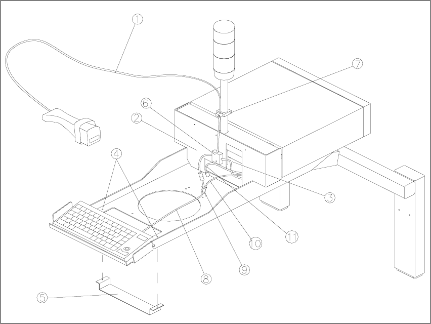
Fig. 2.7.1 Attaching the Component Scanner to PC Carriers 2 and 3
Key:
1. Hand-held scanner
2. Short cable
3. Long cable
4. Holes to fasten the bar-code bracket
5. Bar-code bracket
6. Signal filter and Velcro fastener
7. Strain relief
8. Keyboard cable
9. Splitting of keyboard cable and trackball cable
10. Trackball cable
11. Cable to the Machine Controller
The signal filter must be fastened as far DOWN as possible: see illustration.