00191099-01.pdf - 第47页
Component B ar-Code Sc anner (Optional) Retrofitting Instructions SIPLACE 80 / S-23 (HM) / HS-50 Issue 06/00 2.8 Component Bar-Code Scanner on SIPLACE 80 S-15/F3 47 CAUTION During th e following d rilling, d o not let an…
Retrofitting Instructions SIPLACE 80 / S-23 (HM) / HS-50 Component Bar-Code Scanner (Optional)
2.8 Component Bar-Code Scanner on SIPLACE 80 S-15/F3 Issue 06/00
46
&RPSRQHQW%DU&RGH6FDQQHURQ6,3/$&(
6)
+DUGZDUH,QVWDOODWLRQ
Å Turn the machine OFF and isolate the machine from the mains (for details: see DANGER text
in Section 2.2).
Å Leave the safety hoods closed.
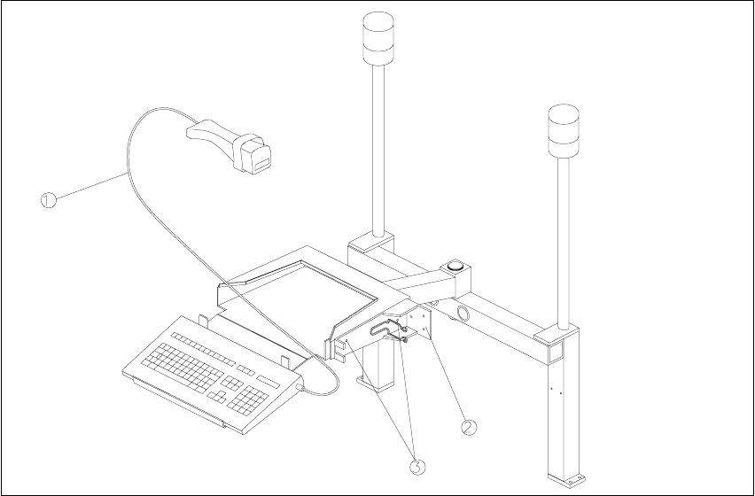
Fig. 2.8.1 PC Carrier for S-15/F3
Key:
1. Hand-held scanner with cable
2. Hand-held scanner bracket
3. Holes to attach the bracket for the hand-held scanner
Å Unplug the plug-and-socket connections on the back of the station monitor.
Å Lift the station monitor off the carrier.
Å Place the bar-code scanner from the retrofit kit (see Section 2.3.3) against the side of the mon-
itor carrier as shown in Fig. 2.8.1 and mark the hole locations on the monitor carrier.

Component Bar-Code Scanner (Optional) Retrofitting Instructions SIPLACE 80 / S-23 (HM) / HS-50
Issue 06/00 2.8 Component Bar-Code Scanner on SIPLACE 80 S-15/F3
47
CAUTION
During the following drilling, do not let any chips drop into the machine and do not damage any
cables.
The safety hoods must remain closed and covered with a cloth so that no chips can pass through
the gaskets of the safety hoods.
Å Cover the middle of the safety hoods with a cloth.
Å Make a hole with an M4 thread at each of the 2 positions marked.
Å Mount the bar-code bracket on the side of the monitor carrier (see Fig. 2.8.1):
2 socket hex head cap screws M4 x 6 DIN 912 and, for each, 2 washers A4.3 DIN 125.
Å EXCHANGE the existing keyboard for the keyboard in the retrofit kit (see Section 2.3.3).
Å Make certain that the warning labels bearing the symbol for a laser and technical data are on
the hand-held scanner (see Section 2.2).
Å Lift the station monitor back onto the carrier.
Å Carefully remove the cover (cloth) on the safety hoods and thoroughly clean the entire area of
the safety hoods with the vacuum cleaner.
Å Place the hand-held scanner on the side of the keyboard (Fig. 2.8.1).
Å Reconnect the plug-and-socket connections on the back of the station monitor.
.H\ERDUG6HWWLQJ
Currently, the keyboards are set to Laser Emulation as standard. To use them on SIPLACE S-15/
F3 machines, however, they have to be changed to Wand Emulation.
Å Turn the little red switch (SW 1) on the bottom of the keyboard from "Programming off" to "Pro-
gramming on".
Å Press the "F9" key (select bar-code scanner type).
Å Press the key combination "Crtl S". This switches the bar-code to Wand Emulation.
Å Set the red switch back to "Programming off".
Å Read the information regarding the bar-code setting in Section 2.8.3 and, if necessary, set an-
other bar-code.

Retrofitting Instructions SIPLACE 80 / S-23 (HM) / HS-50 Component Bar-Code Scanner (Optional)
2.8 Component Bar-Code Scanner on SIPLACE 80 S-15/F3 Issue 06/00
48
%DU&RGH6HWWLQJV
This section is applicable for all SIPLACE 80 and S-23 (HM) machines and HS-50 machines:
The hand-held scanner or the keyboard can recognize a large number of different types of bar-
codes. Different parameters can be set in each bar-code type.
The scanner and keyboard can store 5 different types of bar-codes. The following types of bar-
codes are set:
– EAN/UPC family with/without ADD ON
– Code 39 (normal / FULL ASCII)
– CODABAR
–INTERLEAVED 2/5
– Normal 2/5 (5 bars)
– In case of S-15/F3: Code 128 is set at the keyboard instead of Normal 2/5 (5 bars). Code 128
is not set on the laser. Scanner or keyboard must be reprogrammed.
NOTE:
If other types are to be used, it will be necessary to reprogram the SCANNERS on
SIPLACE 80 S-20/S-15/F4/F4_6 / F5 (HM) and SIPLACE S-23 (HM) and HS-50
and
the scanner AND the keyboard on SIPLACE 80 S-15/F3.
To reprogram the component bar-code (or the keyboard) proceed as indicated in the Program-
ming Flow Chart in the User Manual accompanying the hand-held scanner (or keyboard).
&RQILJXULQJWKH%DU&RGH
Configure the component bar-code as described in Section12 of the relevant User Manual,
"Means of Production, Station Configuration and Line Configuration" and also in Section 11 of the
User Manual for the station computer, "Station Expansions and Options".