00191099-01.pdf - 第52页
Retrofitting I nstructions SIPLACE 80 / S-23 (HM) / HS-50 Component Bar-Code Scanner (Optional) 2.9 Retrofitti ng Sequence on SIPLACE HS-50 Issue 06/00 52 Fig. 2.9.3 Pulling Out the Plug-In Power S upply Module; Instal…
Component Bar-Code Scanner (Optional) Retrofitting Instructions SIPLACE 80 / S-23 (HM) / HS-50
Issue 06/00 2.9 Retrofitting Sequence on SIPLACE HS-50
51
Fig. 2.9.2 Plug-In Power Supply Module for HS-50: Detaching the Plug-In Module
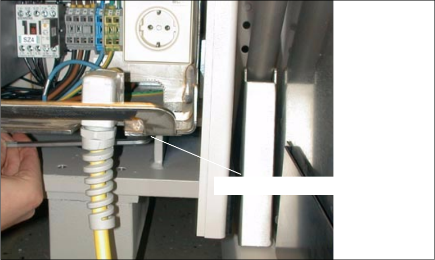
Å At the Bottom Right, loosen the screw fastening the plug-in power supply module (socket hex
head cap screw M8 / size 6).
6RFNHWKH[KHDGVFUHZ0
Retrofitting Instructions SIPLACE 80 / S-23 (HM) / HS-50 Component Bar-Code Scanner (Optional)
2.9 Retrofitting Sequence on SIPLACE HS-50 Issue 06/00
52
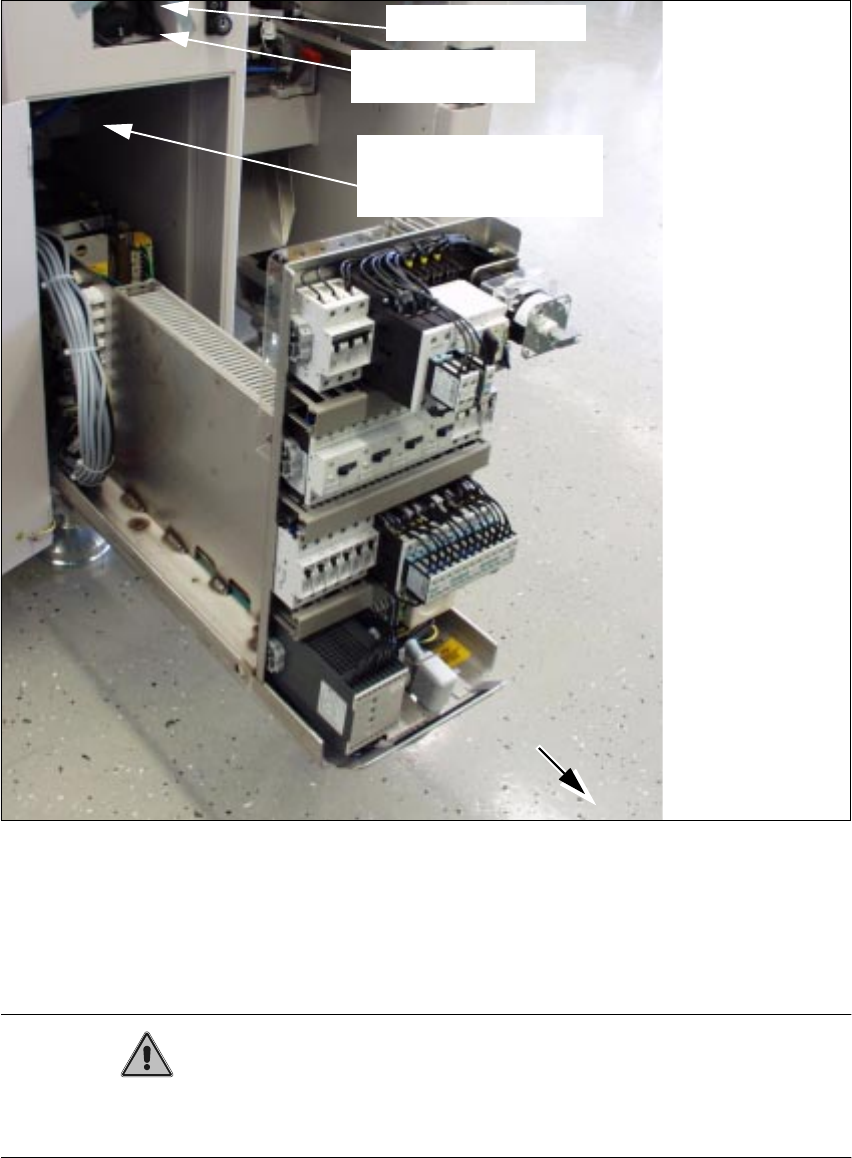
Fig. 2.9.3 Pulling Out the Plug-In Power Supply Module; Installation Side Comp. Bar-Code Scanner
Å Pull the plug-in power supply module out as far as possible (see Fig. 2.9.3).
This requires a rather large amount of force.
When it is pulled out, the module projects past the guides.
CAUTION
The plug-in power supply module must be covered quickly and carefully to avoid any short-circuit
due to a dropped tool, etc.
scanner
Signal filter to be
attached
component bar-code
Cables to be attached
Hand-held scanner
Component Bar-Code Scanner (Optional) Retrofitting Instructions SIPLACE 80 / S-23 (HM) / HS-50
Issue 06/00 2.9 Retrofitting Sequence on SIPLACE HS-50
53
Å In addition to the protective measures to be taken as per DIN EN 60204, Part 1, also cover the
plug-in power supply module with a heavy cloth (see CAUTION, above).
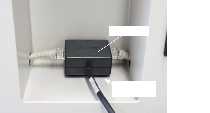
Fig. 2.9.4 Mounting the Signal Filter in the Indentation in the Machine Base
Å Place one portion of the adhesive Velcro fastener from the retrofit kit on the horizontal surface
of the indentation (Section 2.3.4) as shown above.
Å Fasten the other portion of the Velcro fastener to the two signal filters from the retrofit kit.
Å Fasten the signal filters to the two operator sides (see "Overview", Fig. 2.9.1) as shown in Fig.
2.9.4.
Å Unplug the existing plug-and-socket connection "Computer cable <-> Y-filter (KB)": see block
diagram, Fig. 2.9.5 and Fig. 2.9.6.
6LJQDOILOWHU
Strip of adhesive
Velcro