88181945-01-06 Technical Reference Manual ( Production Iss 06 December 2020).pdf - 第3页
3 Issue 06 , December 2020 Table of Contents W ARNING N OTICES ................................................................................................ .................................... 4 INSTALLATION ........…
The legal form of this notice can be read at www.asm-smt.com/disclaimer
This information is provided in good faith; it is believed to be accurate and sufficient for the intended purpose
This information remains the property of GroupASMAS
ASMAS Group are not liable for the consequences of applying this information
ASMAS Group are free to alter this information without notice
We have reviewed the contents of this publication to ensure consistency with the hardware and software de-
scribed. Since variance cannot be precluded entirely, we cannot guarantee full consistency. However, the informa-
tion in this publication is reviewed regularly and any necessary corrections are included in subsequent editions.
Copyright © Assembly SystemsASM Singapore Pte Ltd Group
ASM Assembly Systems Weymouth Ltd
11 Albany Road
Granby Industrial Estate
Weymouth, Dorset
DT TH4 9 , England
Item no.: 88181945-01-06
www. .comasm-smt Printed by Assembly SystemsASM
®
Dir t Ball Placement , Grid-Lok , HawkEye , Interactiv , ProFlow , PumpPrinting and VectorGuard
are trademarks of Assembly Systems Pte Ltd.
EK
TM TM TM TM TM TM TM
ASM
Microsoft is a registered trademark of Microsoft Inc.
Windows 10 IoT Enterprise are trademarks of Microsoft Inc.
All other brand and product names are trademarks or registered trademarks of their respective holders.
is a registered trademark of Assembly Systems Pte Ltd.ASM
Please note the following:

3 Issue 06, December 2020
Table of Contents
WARNING NOTICES .................................................................................................................................... 4
INSTALLATION ........................................................................................................................................... 6
TECHNICAL DATA ....................................................................................................................................... 6
SERVICES REQUIRED .................................................................................................................................. 7
TRANSPORTATION ...................................................................................................................................... 7
CONDENSATE COLLECTION ......................................................................................................................... 9
INDICATOR BEACON .................................................................................................................................. 10
TEMPERATURE SENSOR LOOM .................................................................................................................. 11
AIR DUCTING HOSE .................................................................................................................................. 12
INSTALLATION .......................................................................................................................................... 14
OPERATION ............................................................................................................................................. 15
INITIALIZING THE MACHINE ........................................................................................................................ 15
DISCONNECT AND SHUTDOWN PERIODS .................................................................................................... 20
PREVENTATIVE MAINTENANCE ............................................................................................................ 21
CHECKING THE DISCHARGE FILTER ........................................................................................................... 21
CONDENSER FAN/COIL ............................................................................................................................. 23
SCHEDULED MAINTENANCE ....................................................................................................................... 24
SPARE PARTS LIST ................................................................................................................................... 25
BEACON/PCB INTERPRETATION AND FAULT ANALYSIS .................................................................... 26
BEACON AND PCB INTERPRETATION ......................................................................................................... 26
DISPLAY AND CONDENSATE ERROR CHECKLIST ......................................................................................... 30
ELECTRICAL FAULTS ................................................................................................................................. 31
DIAGNOSTIC FLOW CHARTS ................................................................................................................. 31
4 Issue 06, December 2020
Safety
Warning Notices
To ensure the safe operation of equipment, all personnel must follow generally accepted
safety procedures. These procedures ensure their own safety and the safety of those
around them. In this manual and on the machine, safety symbols of the type described
below are shown when a potential hazard is given, the advisory notices should be
heeded at all times.
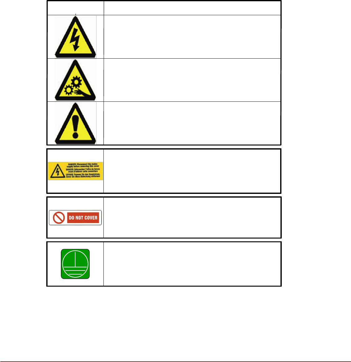
SYMBOL
DEFINITION
WARNING
ELECTRICAL HAZARD. High electrical voltage is present
that could cause injury or death. Do not remove protective
covers from the equipment housings or override protective
devices.
WARNING
BEWARE OF MOVING PARTS. Rotating fans are present that
could cause injury or death. Switch off power to fan motors
before removing panels and proceed with caution.
CAUTION
Refers to a possibly harmful situation. If not avoided,
damage could be caused to the product or something in its
environment.
WARNING - DANGER
Ensure machine is isolated from all sources of electrical
energy before removing access covers for service and
maintenance.
CAUTION - DO NOT COVER
Care must be taken to ensure airflow through the Air
Conditioning Unit is not obstructed. Over-heating and
possible failure of the machine may occur if not observed.
DO NOT COVER
PROTECTIVE EARTH CONNECTION
If it is necessary to remove Protective Earth Connections to
enable repair/maintenance, care should be taken to ensure
connections are remade on completion and prior to
reinstating the machine power supply.