88181945-01-06 Technical Reference Manual ( Production Iss 06 December 2020).pdf - 第32页
Fault I nd ication - ACU MCB Has Tripped YES NO O Check ma in s supply voltage i s with in operating range of 207 – 253V. Isolate mains supply from TCM, res et 6A ACU MCB and power up T CM . Is the ACU functioning correc…
31 Issue 06, December 2020
Electrical Faults
Error
Remedy
Red Beacon (No Blue)
(TCM Shutdown)
Check ACU circuit breaker is closed.
Check heater circuit breaker is closed
Heater Enclosure Thermal Trip may have operated
due to an over temperature condition.
Investigate cause of failure. ESCALATE
No display on Beacon or
Controller
Check Control Module circuit breaker is closed.
WARNING
ELECTRICAL HAZARD. Ensure Isolator is in the OFF
position before opening access door. The following
procedures should only be carried out by suitable
personnel.
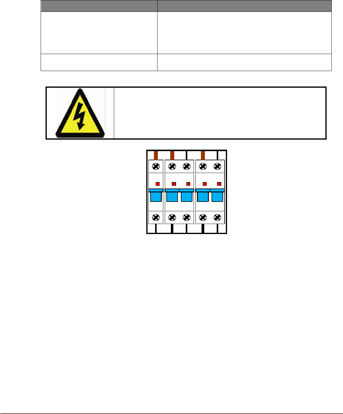
I-ON I-ON I-ON I-ON I-ON
C1 C10 C6
FIG 28
Circuit Breakers (located on the Control Module) protect components and wiring in the
24Vdc Control (C1), Heater (C10), and Air Conditioner Unit (C6) circuits from excessive
currents. Should a circuit breaker open, the cause must be investigated before closing
and re-energizing the circuit. ESCALATE if fault persists and Circuit Breaker will not
remain closed.
Diagnostic Flow Charts
Flow charts on following pages
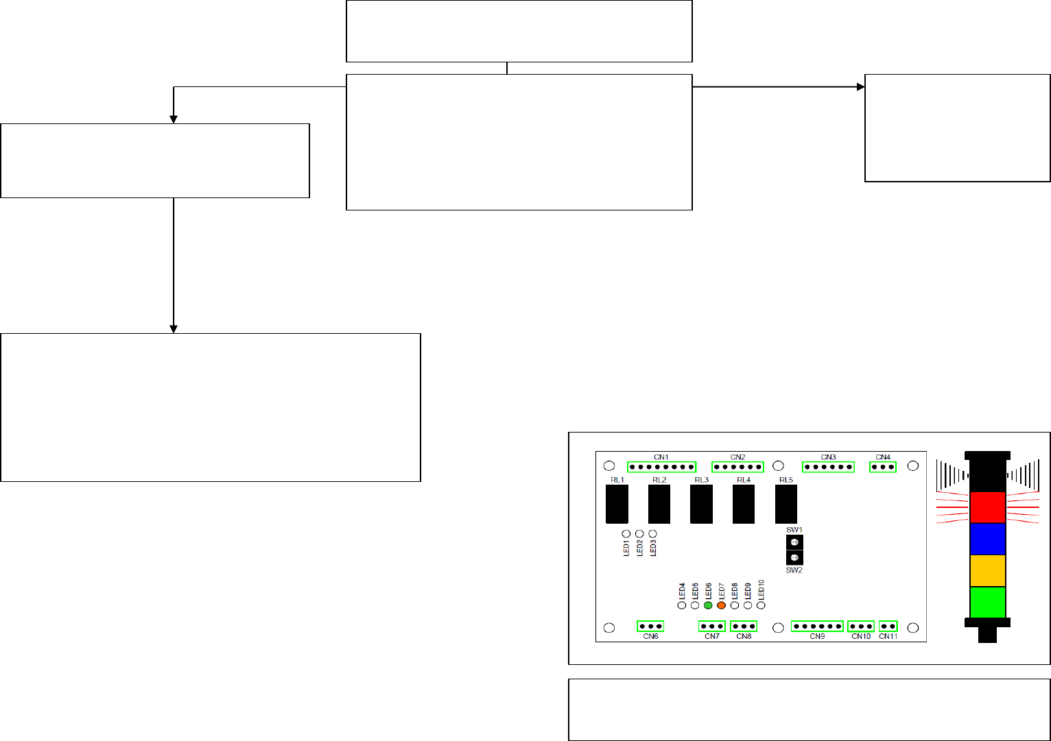
Fault Indication - ACU MCB Has
Tripped
YES
NO
O
Check mains supply voltage is within
operating range of 207 – 253V.
Isolate mains supply from TCM, reset 6A
ACU MCB and power up TCM.
Is the ACU functioning correctly now?
Is fault indication still present?
Replace ACU
Part No. 202340
See install procedure
YES
Use TCM CCT DWG 181948 as reference for further
fault finding.
Check following components for failure:
Control PCB Part No. 181984
6A MCB Part No. 181985
Contactor Part No. 181989.
Use TCM CCT DWG 181948 as reference for further fault
finding.
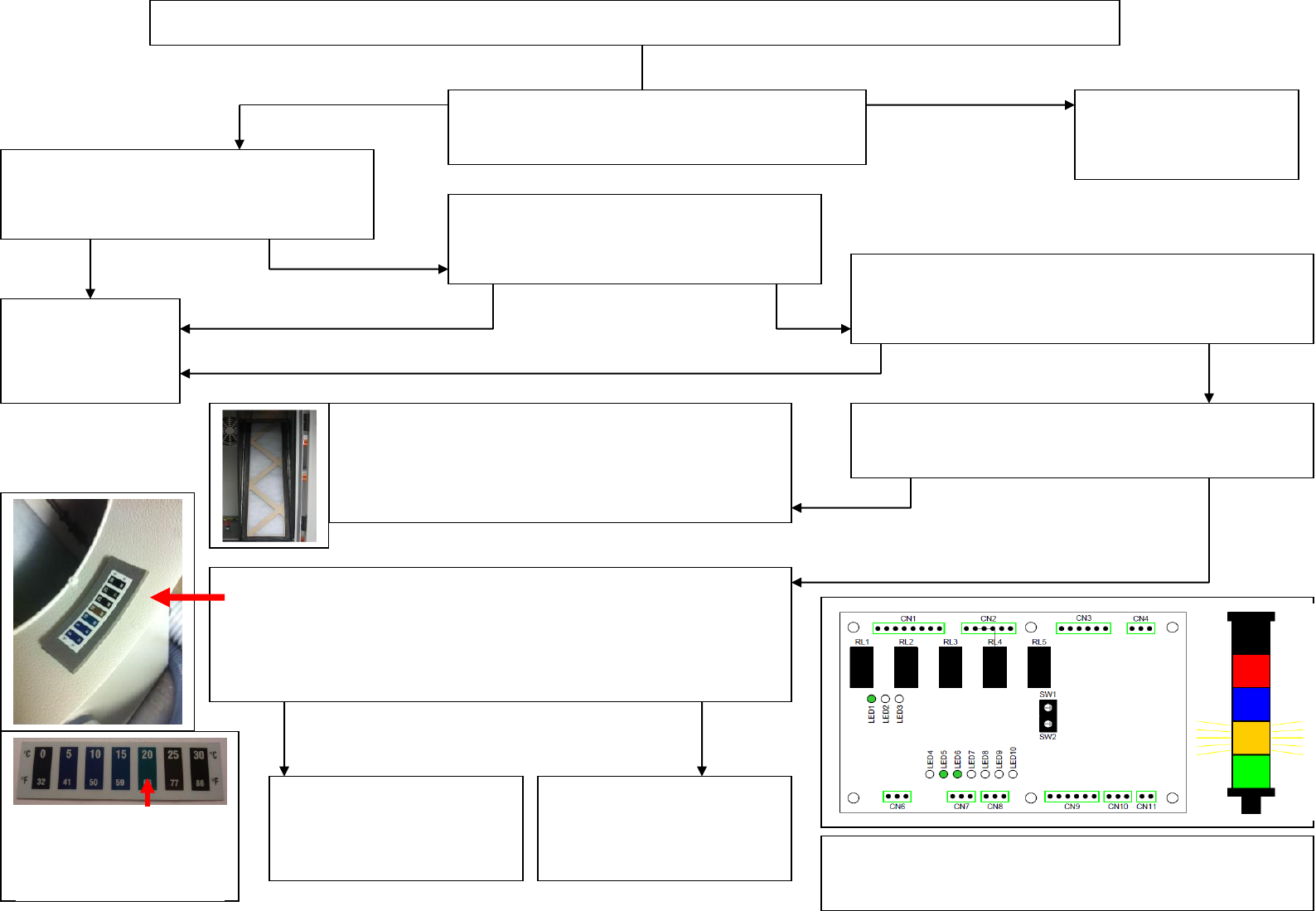
Amber Beacon ON for more than 30 minutes whilst TCM cooling down to SV
YES
NO
Is the SV (Set Value) within + or - 8°C of the
factory ambient temperature?
Is the mains supply to the TCM within
specification (230V +/- 10% (207V to 253V
working range) 50/60Hz?
Change SV to be
within + or - 8°C of
ambient.
Are all printer covers fitted including side
safety covers?
Are both the flexible ducts correctly fitted and
arranged so that routing to the printer is as short and
direct as possible?
YES
NO
NO
Rectify
YES
NO
NO
Remove Air In flexible duct from printer. Is there a
strong airflow exiting the duct?
YES
Check filter is not blocked. Part No. 181944
If filter is OK then evaporator fan in the ACU may
have failed.
Replace ACU Part No. 202340 See install procedure
Check temperature of the processed air entering the printer.
See Temperature sensitive label located inside top TCM duct port.
Green coloured block indicates temperature. With heaters off a
correctly functioning ACU reading is 10 –15°C.
Is temperature higher or lower than SV (Set Value)?
YES
Replace ACU
Part No. 202340
See install procedure
Fit temperature sensor
upgrade.
Refer to Web for latest
MPU
HIGHER
LOWER
Use TCM CCT DWG 181948 as reference for
further fault finding.
Indicating 20°C
Strip not fitted? Order
Part No. 215458