TR7600 SIII_Series_Installation_en_v_2_0_2.pdf - 第20页
Test Research, Inc . TR7600 SII I Series U ser Guide – I nstallatio n 10 Figure 16: Palette Slots Allo w Fork to Be Inserted in One Direction 16) The n put the machine in the right position. Size o f the m ain machine …
Test Research, Inc.
9 TR7600 SIII Series User Guide – Installation
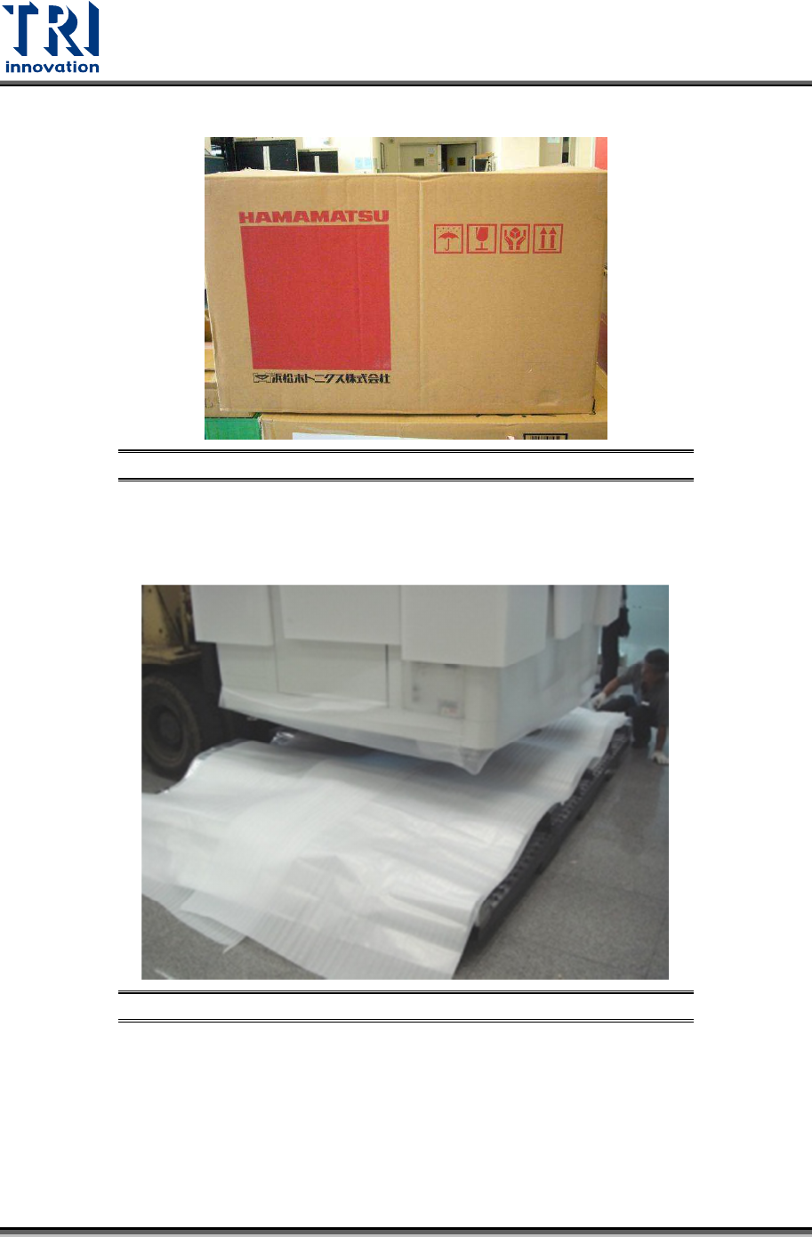
14) Note that the X-ray tube should only be set down as demonstrated below.
Figure 14: Keep the X-ray Tube Facing Up and Handle Carefully
15) Use a fork lift to remove the main machine. You have to watch the direction that allows
you to insert the forks into the slots.
Figure 15: Remove the Machine
Test Research, Inc.
TR7600 SIII Series User Guide – Installation 10
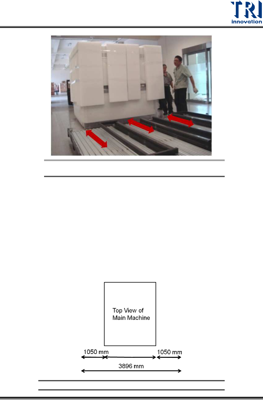
Figure 16: Palette Slots Allow Fork to Be Inserted in One
Direction
16) Then put the machine in the right position.
Size of the main machine is W57.9in. × D83.1in. × H77.8in. (1.470m × 2.110m ×
1.975m) which does not include the height of signal tower of 20.1in. (0.51 m).
You should reserve a space that is at least 154 inches wide × 176.5 inches deep
× 98.4 inches high (3.89m × 4.48m × 2.5m) for daily operation.
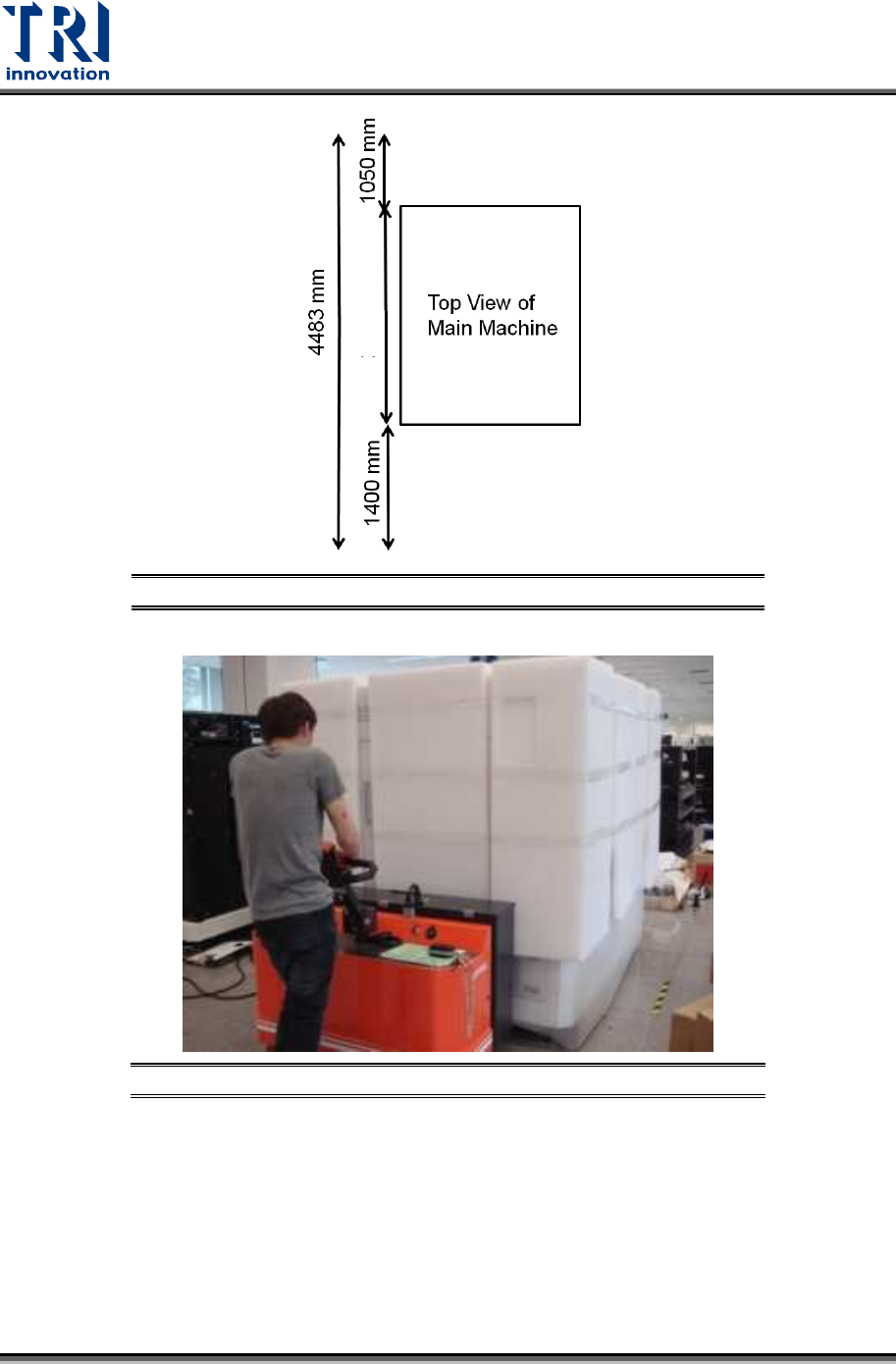
If you want to put the repair station next to the main machine, you should
reserve a space that is at least 188.8 inches wide × 176.5 inches deep × 98.4
inches high (4.79 m × 4.48 m × 2.5 m) for daily operation.
Additionally, you can also adjust the reserved space according to your upstream and
downstream machines.
Figure 17: Reserved Space for Daily Operation
1470 mm
Test Research, Inc.
11 TR7600 SIII Series User Guide – Installation
Figure 18: Reserved Space for Daily Operation
Figure 19: Put the Machine In The Right Position
17) Remove the remaining packing materials.
18) Adjust the height of the machine. Please use the fork lift to lift the machine first and then
adjust the height of pads.
2110 mm