Sonic Buzzer S F C - Serie.pdf - 第27页
SOKO 2 Retrofit instructions SOKO Sonic Buzzer SIPLACE S / F / C-series 04/2006 Edition 27 : Mount the control unit on the to p hat rail. Pay a ttention that the opener from the control unit is in the cutout of the cable…
2 Retrofit instructions SOKO Sonic Buzzer SIPLACE S / F / C-series SOKO
04/2006 Edition
26
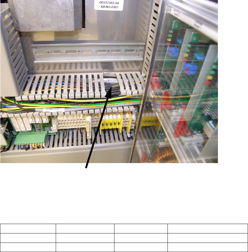
: Cut off two pieces from the cable duct where later is placed the opener from the control unit.
2
2
: Connect the 2-core cable to the control unit as follows described:
2
2
2
2
2
2
2
2
2
Wire colour
Input/ Output Function Connectors of control unit
Brown
Output + 24 V Q1
White
Output Ground (0V) M
Removed pieces
SOKO 2 Retrofit instructions SOKO Sonic Buzzer SIPLACE S / F / C-series
04/2006 Edition
27
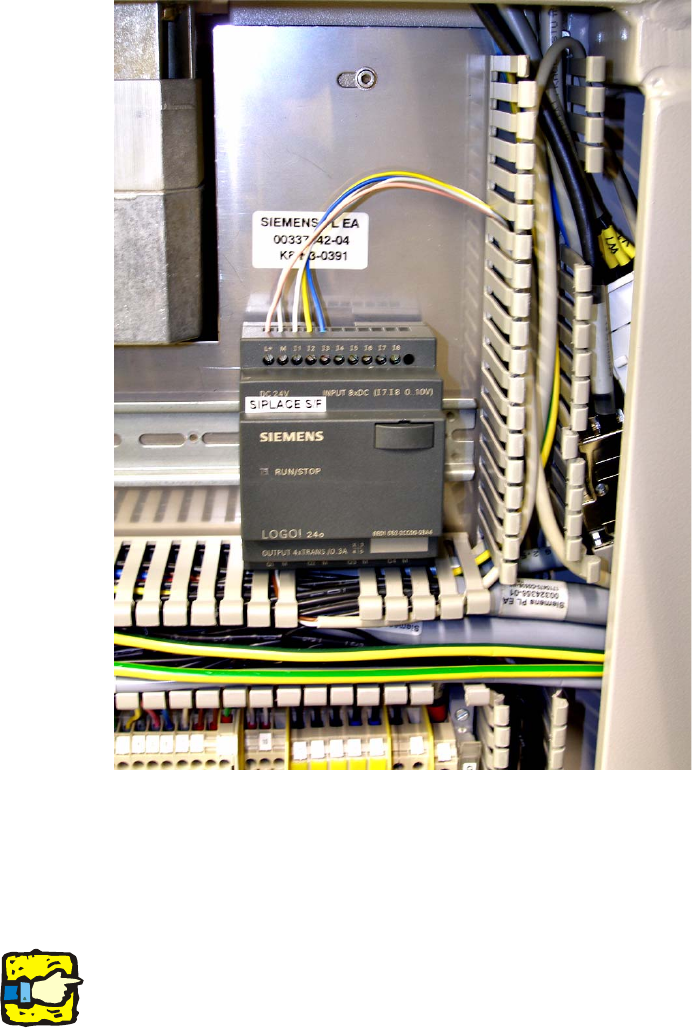
: Mount the control unit on the top hat rail. Pay attention that the opener from the control unit is
in the cutout of the cable duct.
2
2
: Route the 7-core cable to location 3.
: Connect the wires as follows described: Besides you have to unplug the wires from the ma-
chine and plug in to the terminal block X11.
2
Pay attention to the machine type. Please see the following table below. Cross out the non used
connector descriptions with a permanent marker. 2
2
: Unplug the white wire from X2ka:1 or X2kc:1 and plug in to the terminal block X11 to the op-
posite side of the white wire.
: Take the free white wire from the terminal block X11 and plug in to X2ka:1 or X2kc:1.

2 Retrofit instructions SOKO Sonic Buzzer SIPLACE S / F / C-series SOKO
04/2006 Edition
28
: Unplug the yellow wire from X2ka:3 or X2kc:3 and plug in to the terminal block X11 to the op-
posite side of the yellow wire.
: Take the free yellow wire from the terminal block X11 and plug in to X2ka:3 or X2kc:3.
: Unplug the violet wire from X1ka:5 or X2kd:5 and plug in to the terminal block X11 to the op-
posite side of the blue wire.
: Take the free blue wire from the terminal block X11 and plug in to X1ka:5 or X2kd:5.
: Plug in the pink wire to X3ka:P+ or X2kc:P+.
: Plug in the grey wire to X4ka:M- or X2kc:M-.
2
2
2
Wire colour
Connectors of control unit Terminal designati-
on for S27HM
Terminal designation for S20/
S23/F5HM/F5/F4/CF/CS
Pink
P+ (+24V) X3ka:P+ X2kc:P+
Grey
(Ground) (0V) X4ka:M- X2kc:M-
White
I1 (Signal light right) X2ka:1 X2kc:1
Yellow
I2 (Signal light left) X2ka:3 X2kc:3
Blue
I3 (Reset or Stop button) X1ka:5 X2kd:5