Sonic Buzzer S F C - Serie.pdf - 第34页
2 Retrofit instructions SOKO Sonic Buzzer SIPLACE S / F / C-series SOKO 04/2006 Edition 34 2.7.2 S-27 H M 2 2 BN Q1 SIEMENS LOGO 10K 1 2 X1 Q2 M Q3 M Q4 M I1 WH I2 YE I3 BU I4 I5 I6 I7 I8 L+ PK WH M M GY Buzzer 200R WH Y…
SOKO 2 Retrofit instructions SOKO Sonic Buzzer SIPLACE S / F / C-series
04/2006 Edition
33
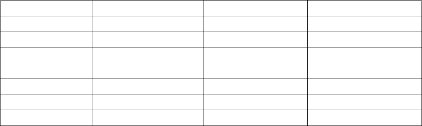
2.7 Circuit diagrams
2.7.1 Control unit
2
Wire colour
Input/ Output Function Terminal designation
Pink
Input + 24V P
Grey
Input Ground (0V) M
White
Input Signal light right I1
Yellow
Input Signal light left I2
Blue
Input Stop or reset I3
Brown
Output +24V Q1
White
Output Ground (0V) M
2 Retrofit instructions SOKO Sonic Buzzer SIPLACE S / F / C-series SOKO
04/2006 Edition
34
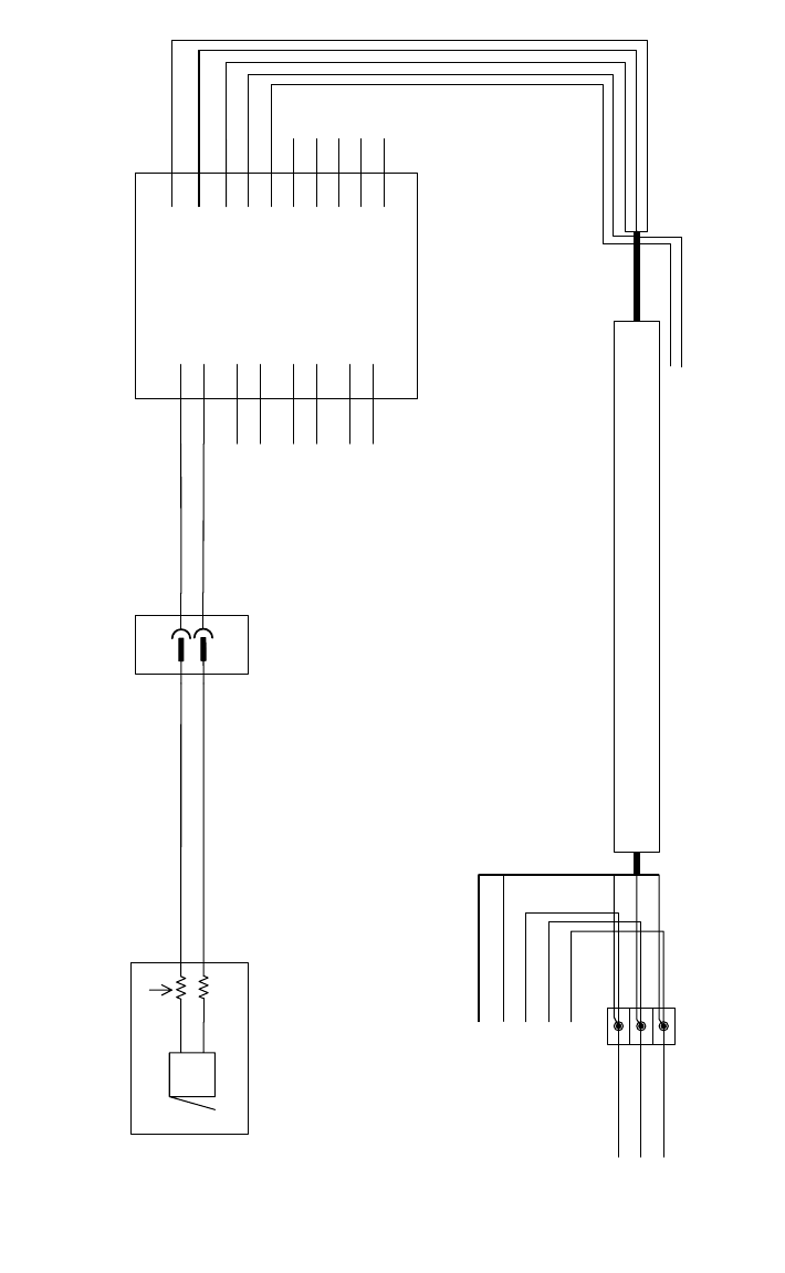
2.7.2 S-27 HM
2
2
BN Q1
SIEMENS
LOGO
10K
1
2
X1
Q2
M
Q3
M
Q4
M
I1 WH
I2 YE
I3 BU
I4
I5
I6
I7
I8
L+ PK
WH M
M GY
Buzzer
200R
WH
YE
BU
PK
GY
X11
X3ka:P
X4ka:M
X2ka:1
X2ka:3
X1ka:5
WH
YE
VT
00321509-xx
00321509-xx
00321432-xx
SOKO 2 Retrofit instructions SOKO Sonic Buzzer SIPLACE S / F / C-series
04/2006 Edition
35
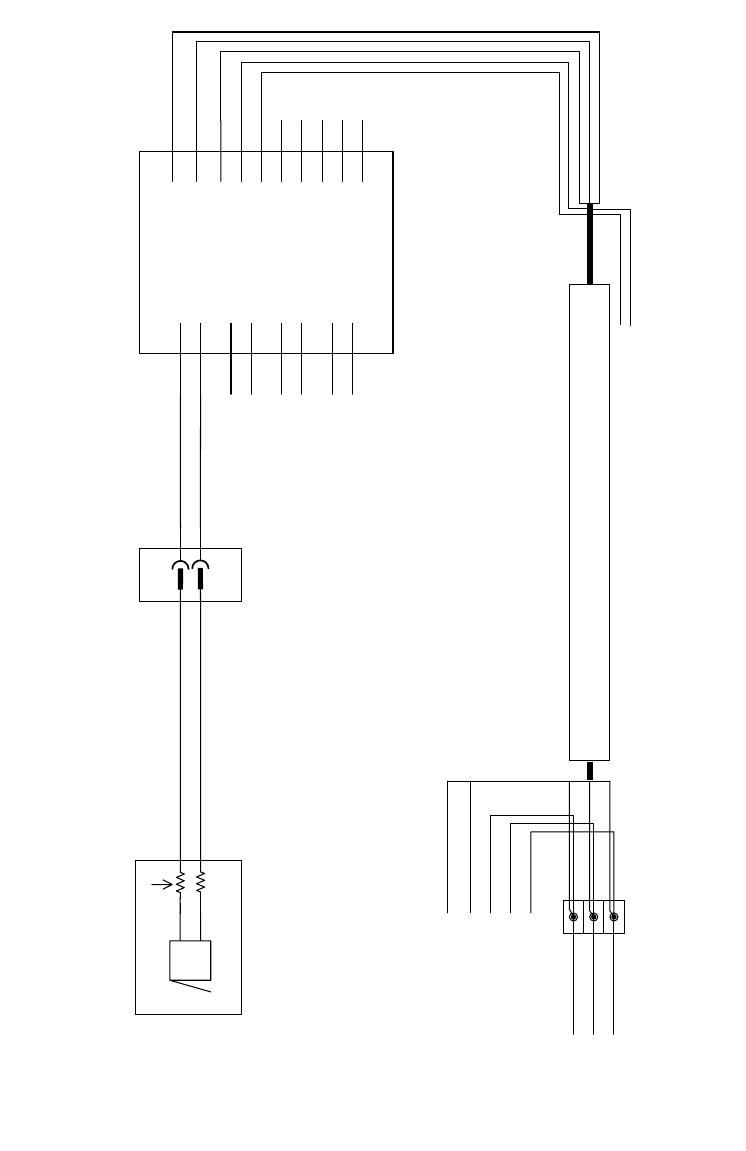
2.7.3 S-20 / S-23 / F4 / F5 / F5 HM / CF / CS
2
2
BN Q1
SIEMENS
LOGO
10K
1
2
X1
Q2
M
Q3
M
Q4
M
I1 WH
I2 YE
I3 BU
I4
I5
I6
I7
I8
L+ PK
WH M
M GY
Buzzer
200R
WH
YE
BU
PK
GY
X11
X2kc:P
X2kc:M
X2kc:1
X2kc:3
X2kd:5
WH
YE
VT
00321509-xx
00321509-xx
00321432-xx