IPC-7721(S).pdf - 第104页
NOTES IPC-7721 Number: 4.2.7 Revision: Date: 2/98 Subject: Conductor Repair , Inner Layer Method P a g e4o f4

15. Coat the top and sides of the replaced conductor with epoxy. The epoxy bonds
the new conductor to the base board material and insulates the conductor.
Continue adding epoxy up to the top surface of the printed wiring board or to
the height of the next internal conductor. (See Figure 6.)
NOTE
A slight overfill of epoxy may be desired to allow for shrinkage when the epoxy
cures.
16. Cure the epoxy per the manufacturer’s instructions.
CAUTION
Some components may be sensitive to high temperature.
17. Add additional conductor foil jumpers if needed and coat with additional epoxy.
18. Continue completing all layers until the top surface of the printed wiring board is
reached. (See Figure 7.)
19. Clean the board as required.
20. Apply surface coating to match prior coating as required.
EVALUATION
1. Visual examination for alignment and overlap of new conductor.
2. Visual examination of epoxy coating for texture and color match.
3. Electrical tests as applicable.
IPC-7721
Number: 4.2.7
Revision:
Date: 2/98
Subject: Conductor Repair, Inner Layer Method
Page3of4

NOTES
IPC-7721
Number: 4.2.7
Revision:
Date: 2/98
Subject: Conductor Repair, Inner Layer Method
Page4of4
OUTLINE
This method is used to sever a conductor or short. A small section of the conduc-
tor is removed forming a break. The width of the break should be at least as wide as
the minimum conductor spacing. A knife or high speed, hand held drill is used. This
method is recommended for surface conductor cuts only. After cutting, the area is
sealed with epoxy.
NOTE
This method is recommended for surface conductor cuts only.
REFERENCES
2.1 Handling Electronic Assemblies
2.2 Cleaning
2.6 Epoxy Mixing and Handling
TOOLS AND MATERIALS
Ball Mills, Carbide
Cleaner
Cleaner Wipes
Color Agent
Continuity Meter
Epoxy
Epoxy Dispensing System
Hand Held Drill
Heat Lamp
Knife
Microscope
Oven
PROCEDURE
1. Identify the conductor or short to be cut. Determine from the artwork or draw-
ings where the best location is to make the break. The width of the break should
at least match the minimum required electrical spacing.
2. Clean the area.
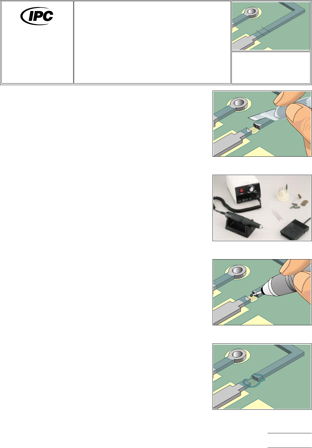
3. Carefully make two small cuts with the knife and remove the short section of
conductor. (See Figure 1.)
NOTE
If desired, remove a second section of the conductor at the opposite end to
eliminate the potential of the conductor acting as an antenna.
4. Select the appropriate size ball mill and insert it into the dental style drill. Set the
speed to high. (See Figure 2.) The ball mill should be approximately the same
width as the conductor to be cut. (See Table 1 for standard ball mill sizes.)
CAUTION
Abrasion operations can generate electrostatic charges.
NOTE
Ball mills should be dental grade carbide steel for precision cutting and long life.
Figure 1 Make two small cuts with a
knife and remove section of conductor.
Figure 2 A high quality, hand held
drill.
Figure 3 Make one or two cuts as
needed to cut conductor.
Figure 4 Completed repair.
7721
Repair and
Modification of
Printed Boards and
Electronic Assemblies
Revision:
Date: 2/98
Conductor Cut,
Surface Conductors
Number: 4.3.1
Product Class: R, F
Skill Level: Advanced
Level of Conformance: High
Material in this manual was voluntarily established by Technical Committees of the IPC. This material is advisory only and its
use or adaptation is entirely voluntary. IPC disclaims all liability of any kind as to the use, application, or adaptation of this
material. Users are also wholly responsible for protecting themselves against all claims or liabilities for patent infringement.
Equipment referenced is for the convenience of the user and does not imply endorsement by the ipc.
Page1of2