IPC-7721(S).pdf - 第128页
NOTES IPC-7721 Number: 4.6.1 Revision: Date: 2/98 Subject: Edge Contact Repair , Epoxy Method P a g e4o f4

16. Trim the extending edge of the new edge contact with a file. File parallel to the
beveled edge until the excess material has been removed. (See Figure 5.)
17. If sealing the lap solder joint connection is required, mix epoxy and coat the lap
solder joint connections. Cure the epoxy per the manufacturer’s instructions.
18. If plating is required refer to appropriate procedure.
19. Apply surface coating to match prior coating as required.
EVALUATION
1. Visual examination, measurement of new pad width and spacing.
2. Electrical continuity measurement.
IPC-7721
Number: 4.6.1
Revision:
Date: 2/98
Subject: Edge Contact Repair, Epoxy Method
Page3of4

NOTES
IPC-7721
Number: 4.6.1
Revision:
Date: 2/98
Subject: Edge Contact Repair, Epoxy Method
Page4of4
OUTLINE
This method is used to replace a damaged edge contact with a new dry film, adhe-
sive backed edge contact. The new edge contact is hot bonded to the printed wir-
ing board surface.
CAUTION
It is essential that the board surface be smooth and flat. If the base material is dam-
aged see appropriate procedure.
NOTE
This method uses commercially available replacement edge contacts. The edge
contacts are fabricated from copper foil and have a dry film adhesive coating on the
back. They are available in hundreds of sizes and shapes and are generally supplied
nickel and gold plated. If a special size or shape is needed they can be custom fab-
ricated.
REFERENCES
2.1 Handling Electronic Assemblies
2.2 Cleaning
2.5 Baking and Preheating
2.6 Epoxy Mixing and Handling
TOOLS & MATERIALS
Bonding Iron
Bonding System
Bonding Tips
Cleaner
Epoxy
File, Finish Grade
Heat Lamp
Polyimide Tape
Knife
Liquid Flux
Microscope
Oven
Replacement Edge Contacts,
Adhesive Backed
Scraper
Solder
Soldering Iron
Tweezers
Wipes
PROCEDURE
1. Clean the area.
2. Remove the defective edge contact and a short length of the connecting con-
ductor. Heat from a soldering iron will allow the old contact to be removed more
easily.
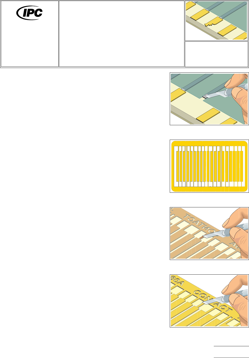
Figure 1 Remove the defective edge
contact and solder resist.
Figure 2 Select a replacement contact
that matches.
Figure 3 Scrape off adhesive bonding
film from solder joint area.
Figure 4 Cut out the new edge
contact.
7721
Repair and
Modification of
Printed Boards and
Electronic Assemblies
Revision:
Date: 2/98
Edge Contact Repair,
Film Adhesive Method
Number: 4.6.2
Product Class: R, F, W, C
Skill Level: Advanced
Level of Conformance: High
Material in this manual was voluntarily established by Technical Committees of the IPC. This material is advisory only and its
use or adaptation is entirely voluntary. IPC disclaims all liability of any kind as to the use, application, or adaptation of this
material. Users are also wholly responsible for protecting themselves against all claims or liabilities for patent infringement.
Equipment referenced is for the convenience of the user and does not imply endorsement by the ipc.
Page1of4