IPC-7721(S).pdf - 第23页
S8.1-1992 as well as the Electronic Industries Association (EIA) in EIA standard RS-471. Note that the absence of a symbol does not necessarily mean that the assembly is not ESD sensitive. When doubt exists about the sen…
occur. All ESD protection techniques and products address
one or both of the two issues.
ESD damage is the result of electrical energy that was gener-
ated from static sources either being applied or in close prox-
imity to ESDS devices. Static sources are all around us. The
degree of static generated is relative to the characteristics of
the source. To generate energy relative motion is required.
This could be contacting, separation, or rubbing of the mate-
rial.
Most of the serious offenders are insulators since they con-
centrate energy where it was generated or applied rather than
allowing it to spread across the surface of the material. Com-
mon materials such as plastic bags or Styrofoam containers
are serious static generators and as such are not to be
allowed in processing areas especially static safe areas. Peel-
ing adhesive tape from a roll can generate 20,000 volts. Even
compressed air nozzles which move air over insulating sur-
faces generate charges.
Destructive static charges are often induced on nearby con-
ductors, such as human skin, and discharged into conduc-
tors. This can happen when a printed board assembly is
touched by a person having a static charge potential. The
electronic assembly can be damaged as the discharge
passes through the conductive pattern to a static sensitive
component. Static discharges may be too low to be felt by
humans (less than 3500 volts), and still damage ESDS
components. Typical static voltage generation is included in
Table 2
2.1.2.1 Warning Labels
Warning labels are available for posting in facilities and place-
ment on devices, assemblies, equipment and packages to
alert people to the possibility of inflicting electrostatic or
electrical overstress damage to the devices they are handling.
An example of frequently encountered labels are shown in
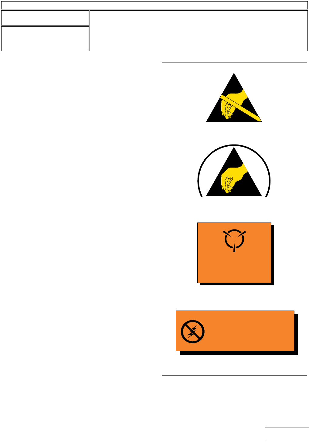
Figure 1.
Symbol (a) ESD susceptibility symbol. A triangle with a reach-
ing hand and a slash across it. This is used to indicate that an
electrical or electronic device or assembly is susceptible to
damage from an ESD event.
Symbol (b) ESD protective symbol. This differs from the ESD
susceptibility symbol in that it has an arc around the outside
of the triangle and no slash across the hand. This is used to
identify items that are specifically designed to provide ESD
protection for ESD sensitive assemblies and devices.
Symbols (a) and (b) identify devices or an assembly as con-
taining devices that are ESD sensitive, and that they must be
handled accordingly. These symbols are promoted by the
ESD association and are described in EOS/ESD standard
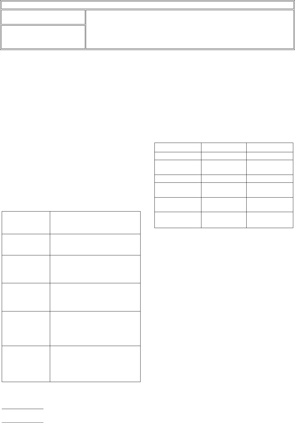
Table 1 Typical Static Charge Sources
Work surfaces Waxed, painted or varnished surfaces
Untreated vinyl and plastics
Glass
Floors Sealed concrete
Waxed or finished wood
Floor tile and carpeting
Clothes and
personnel
Non-ESD smocks
Synthetic materials
Non-ESD Shoes
Hair
Chairs Finished wood
Vinyl
Fiberglass
Non-conductive wheels
Packaging and
handling materials
Plastic bags, wraps, envelopes
Bubble wrap, foam
Styrofoam
Non-ESD totes, trays, boxes, parts
bins
Assembly tools and
materials
Pressure sprays
Compressed air
Synthetic brushes
Heat guns, blowers
Copiers, printers
Table 2 Typical Static Voltage Generation
Source 10-20% humidity 65-90% humidity
Walking on carpet 35,000 volts 1,500 volts
Walking on vinyl
flooring
12,000 volts 250 volts
Worker at a bench 6,000 volts 100 volts
Vinyl envelopes
(Work Instructions)
7,000 volts 600 volts
Plastic bag picked
up from the bench
20,000 volts 1,200 volts
Work chair with
foam pad
18,000 volts 1,500 volts
IPC-7721
Number: 2.1
Revision:
Date: 2/98
Subject: Handling Electronic Assemblies
Page2of8
S8.1-1992 as well as the Electronic Industries Association
(EIA) in EIA standard RS-471.
Note that the absence of a symbol does not necessarily mean
that the assembly is not ESD sensitive. When doubt exists
about the sensitivity of an assembly, it must be handled
as a sensitive device until it is determined otherwise.
Recommend removing the reference symbols c and d since
they were removed from the MIL specs over 10 years ago.
Symbol (c) covers not only electrostatic fields, but electromag-
netic and magnetic fields as well. The use of this symbol to
designate ESD is discouraged since it does not specifically
identify EOS/ESD sensitivity.
Symbol (d) has been used widely as an ESD symbol. The
standard meaning for the lightning bolt symbol is high voltage
in the context of electrical utility power, and typically damag-
ing to personnel. For example, UL-1244 (and IEC-348)
requires that a lightening bolt label be placed near high volt-
age terminals on test equipment. Unfortunately, this symbol is
encountered quite often to designate static sensitive devices.
The use of a lightning bolt to designate ESD is discour-
aged to avoid possible dangerous confusion.
2.1.2.2 ESD Protective Materials
ESDS components and assemblies must be protected from
static sources when not being worked on in static safe envi-
ronments or work stations. This protection could be conduc-
tive static-shielding boxes, bags or wraps.
ESDS items must be removed from their protective enclo-
sures only at static safe work stations.
It is important to understand the difference between the three
types of protective enclosure material: (1) static shielding (or
barrier packaging), (2) antistatic, and (3) static dissipative
materials.
Static shielding packaging will prevent an electrostatic dis-
charge from passing through the package and into the
assembly causing damage.
Antistatic packaging materials are used to provide inex-
pensive cushioning and intermediate packaging for ESDS
items. Antistatic materials do not generate charges when
motion is applied. However, if an electrostatic discharge
occurs, it could pass through the packaging and into the part
or assembly, causing EOS/ESD damage to ESDS compo-
nents.
IPC-610-001
Figure 1 Frequently Encountered EOS/ESD Warning
Labels
▼
▼
▼
CAUTION
SENSITIVE ELECTRONIC DEVICES
DO NOT SHIP OR STORE NEAR STRONG
ELECTROSTATIC, ELECTROMAGNETIC,
MAGNETIC OR RADIOACTIVE FIELDS
(c) MIL-STD-129H Symbol
CAUTION
_
STATIC
ELECTRICITY CAN DAMAGE
CONTENTS
_
OPEN ONLY
AT STATIC-FREE STATION
(b) ESD Protective Symbol
(d) No Official Status
(a) ESD Susceptibility Symbol
IPC-7721
Number: 2.1
Revision:
Date: 2/98
Subject: Handling Electronic Assemblies
Page3of8
Static dissipative materials have enough conductivity to
allow applied charges to dissipate over the surface relieving
hot spots of energy. Parts leaving an EOS/ESD protected
work area must be overpacked in static shielding materials,
which normally also have static dissipative and antistatic
materials inside.
Do not be misled by the ‘‘color’’ of packaging materials. It is
widely assumed that ‘‘black’’ packaging is static shielding or
conductive and that ‘‘pink’’ packaging is antistatic in nature.
While that may be generally true, it can be misleading. In addi-
tion, there are many new clear materials now on the market
that may be antistatic and even static shielding. At one time,
it could be assumed that clear packing materials introduced
into the manufacturing operation would represent an EOS/
ESD hazard. This is not necessarily the case now.
Caution: Some static shielding and antistatic materials and
some topical antistatic solutions may affect the solderability of
assemblies, components, and materials in process. Select
only non-contaminating packaging and handling materials for
in-process assemblies and use them with regard for the ven-
dors instructions. Solvent cleaning of static dissipative or anti-
static surfaces can degrade their ESD performance. Follow
the manufacturers recommendations for cleaning.
2.1.3 Anti-Static Work Station
An EOS/ESD safe work station prevents damage to sensitive
components from spikes and static discharges while opera-
tions are being performed. Safe work stations should include
EOS damage prevention by avoiding spike generating repair,
manufacturing or testing equipment. Soldering irons, solder
extractors and testing instruments can generate energy of suf-
ficient levels to destroy extremely sensitive components and
seriously degrade others.
For ESD protection, a path-to-ground must be provided to
neutralize static charges that might otherwise discharge to a
device or assembly. ESD safe work stations also have static
dissipative or antistatic work surfaces which are connected to
a common ground. Provisions are also made for grounding
the worker’s skin, preferably via a wrist strap to eliminate
charges generated on the skin or clothing.
Provision must be made in the grounding system to protect
the worker from live circuitry as the result of carelessness or
equipment failure. This is commonly accomplished through
resistance in line with the ground path, which also slows the
charge decay time to prevent sparks or surges of energy from
ESD sources. Additionally, a survey must be performed of the
available voltage sources that could be encountered at the
work station to provide adequate protection from personnel
electrical hazards.
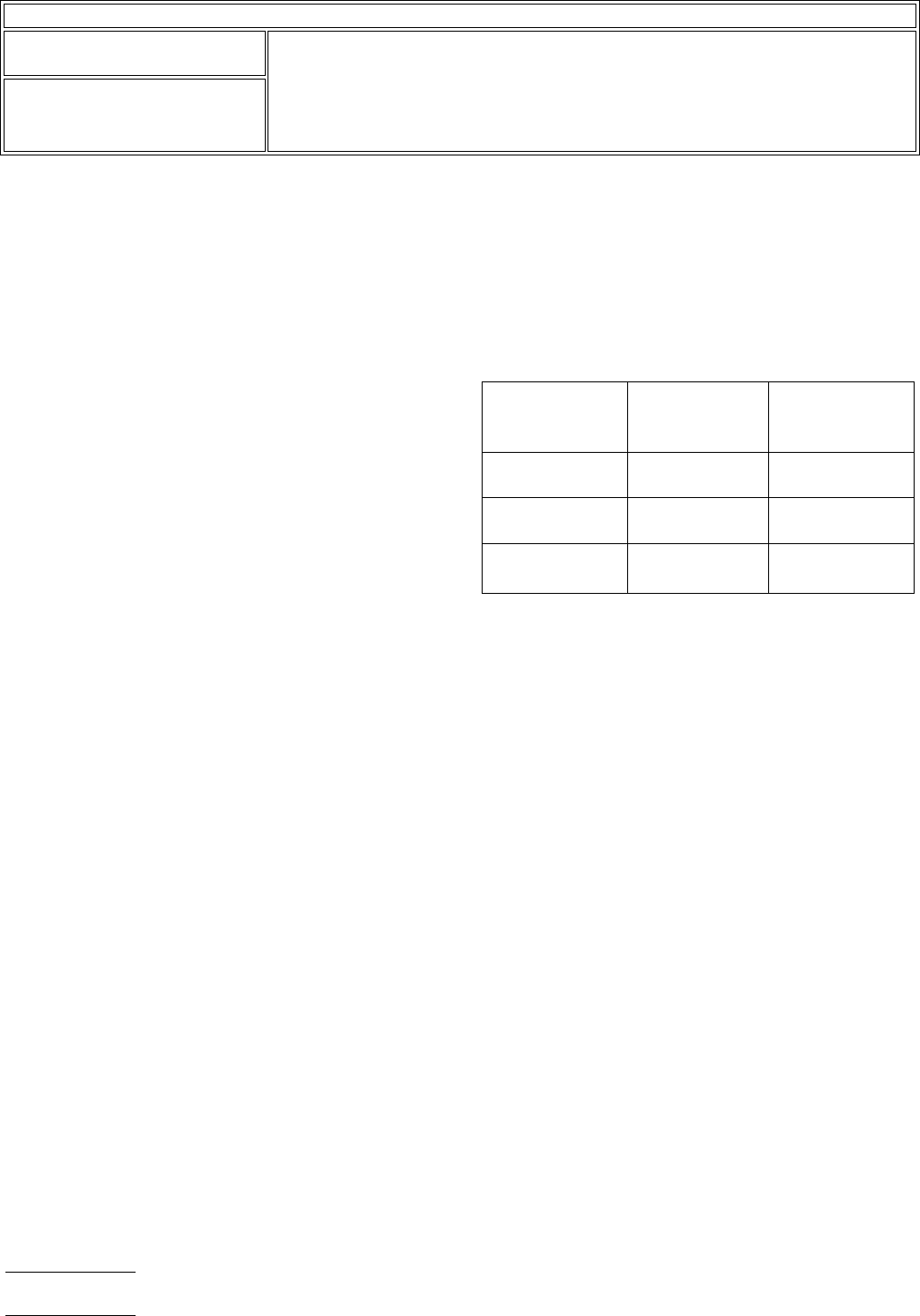
For maximum allowable resistance and discharge times for
static safe operations, see Table 3.
Note: the selection of resistance values are to be based on
the available voltages at the station to ensure personnel safety
as well as to provide adequate decay or discharge time for
ESD potentials.
Examples of static safe work stations are shown in Figures 2
and 3. When necessary, air ionizers may be required for more
sensitive applications. The selection, location, and use proce-
dures for ionizers must be followed to ensure their effective-
ness.
Keep static dissipative or antistatic work station(s) free of
static generating materials such as styrofoam, plastic solder
removers, sheet protectors, plastic or paper notebook folders,
and employees personal items.
Periodically check EOS/ESD work stations to make sure they
work. EOS/ESD assembly and personnel hazards can be
caused by improper grounding methods or by an oxide
build-up on grounding connectors. Tools and equipment must
be periodically checked and maintained to ensure proper
operation.
Particular care must be given to ‘‘third wire’’ ground termina-
tions. Frequently, instead of being at workbench or earth
potential, the third wire ground may have a ‘‘floating’’ poten-
tial of 80 to 100 volts. This 80 to 100 volt potential between
an electronic assembly on a properly grounded EOS/ESD
work station and a third wire grounded electrical tool may
Table 3 Maximum Allowable Resistance and
Discharge Times for Static Safe Operations
Reading from
Operator
Through
Maximum
Tolerable
Resistance
Maximum
Acceptable
Discharge Time
Floor mat to
ground
1000 megohms Less than 1 sec.
Table mat to
ground
1000 megohms Less than 1 sec.
Wrist strap to
ground
100 megohms Less than 0.1 sec.
IPC-7721
Number: 2.1
Revision:
Date: 2/98
Subject: Handling Electronic Assemblies
Page4of8