SOM-1651-002.pdf - 第4页
Contents Page 0206-001 3 Tg0754-PM-SO Before Use ................................................................................................... 1 Contents ............................................................…

Before Use
• Identifying Alert Icons
: This symbol mark represents danger or prompts
warning.
: This symbol mark represents prohibited operations.
: This symbol mark represents forced operations or
instructions.
2. Explained in this manual are only the items different from
those in the instruction manual of the TIM-X100.
Use the instruction manual of the TIM-X100 together with this
manual.
3. The contents of this manual are subject to change without
prior notice.
Please contact our marketing department or sales agent for
detailed information about this product.
0206-001 2 Tg0754-PM-SO

Contents
Page
0206-001 3 Tg0754-PM-SO
Before Use ................................................................................................... 1
Contents ....................................................................................................... 3
1. Scope ..................................................................................................... 4
2. Specifications ......................................................................................... 4
3. Rough View ............................................................................................ 6
3.1 Rough View and Names ................................................................... 6
3.2 Installation Position ........................................................................... 8
4. Scope of Actions .................................................................................... 9
5. Preparation before Operation................................................................. 10
5.1 Component Library Data ................................................................... 10
5.2 Performance Check .......................................................................... 11
6. Component Removal Procedure ........................................................... 13
6.1 Rejected Components on Recycle Conveyor ................................... 13
6.2 Rejected Components in Component Storage Box .......................... 14
7. Rejected Component Discharge Offset ................................................. 15
8. Troubleshooting ..................................................................................... 17
8.1 Scope ................................................................................................. 17
8.1.1 Troubleshooting ....................................................................... 17
8.1.2 "CHECK" Windows .................................................................. 17
8.1.3 "CHECK" List ........................................................................... 17
8.1.4 "ERROR" Windows .................................................................. 17
8.2 Troubleshooting after "ERROR" Window (Error ID) .......................... 18
8.2.1 Typical Description ................................................................... 18
8.2.2 Error IDs and Controlled Areas ................................................ 19
8.2.3 Error IDs and Remedial Procedures ........................................ 20
9. Materials ................................................................................................. 21
9.1 Parts Location .................................................................................... 21
9.2 Location of Sensors and Loads ......................................................... 22
9.3 Electrical Circuit Diagrams ................................................................. 23
Motor Circuit Diagram for Recycle Conveyor B ................................. 23
I/O Circuit Daiagram for Recycle Conveyor B ................................... 25
4 Tg0754-PM-SO0206-001
1. Scope
This recycle conveyor machine has a conveyor to transfer rejected
components to the operator side, as they are and without any dam-
age. That happens when the component recognition error, in the multi-
functional mounter TIM-X100, judges the picked-up component to be
unsuitable for placement. It also has a component storage box to
store the rejected component.
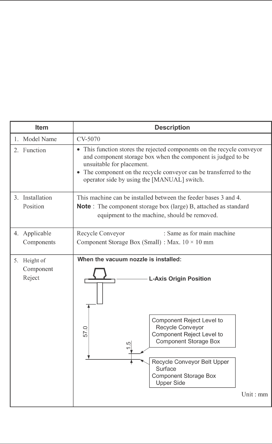
2. Specifications
Table 1
1. Scope