SOM-1651-002.pdf - 第8页
7 Tg0754-PM-SO 0206-001 3.1 Rough View and Names *4 [MANUAL] Switch This [MANUAL] switch operates the recycle conveyor . It is used when the component discharged by the head is removed. * 5 LOCK Lever This lever is used …
6 Tg0754-PM-SO0206-001
3. Rough View
3. Rough View
3.1 Rough View and Names
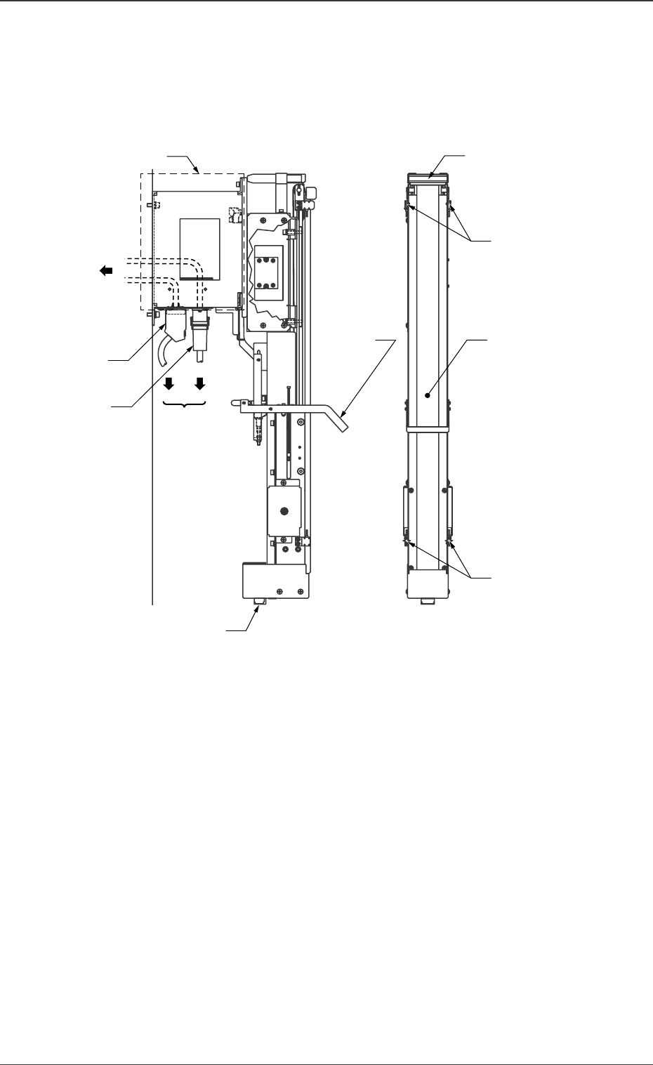
*1 Attachment for Installation
This attachment is used for installing the recycle conveyor.
*2 Signal Connector
This is a signal connector between the recycle conveyor and TIM-
X100.
*3 Power Connector
This connector is used for supplying power to the recycle con-
veyor.
Fig. 1 Recycle Conveyor Rough View
*6 Component
Storage Box (Small)
*1 Attachment for
Installation
*8 Conveyor Belt
*4 [MANUAL] Switch
(Outside of TIM-X100)
(Inside of TIM-X100)
*5 LOCK
*2 Signal
Connector
*3 Power
Connector
*9 Recycle Conveyor
Component Full
Detection Sensor
(-BPH652)
*7 Recycle Conveyor
To TIM-X100
To Recycle
Conveyor
Component Discharge
Position Detection
Sensor (-BPH651)
Lever

7 Tg0754-PM-SO0206-001
3.1 Rough View and Names
*4 [MANUAL] Switch
This [MANUAL] switch operates the recycle conveyor.
It is used when the component discharged by the head is removed.
*5 LOCK Lever
This lever is used to lock the recycle conveyor.
*6 Component Storage Box (Small)
Components with the size of 10 × 10 mm or less are stored in the
box by a setting on the component library data.
*7 Recycle Conveyor Component Discharge Position Detec-
tion Sensor (-BPH651)
This sensor detects whether or not the component is discharged
normally on the recycle conveyor.
*8 Conveyor Belt
This conveyor belt transfers the components to the operator side.
*9 Recycle Conveyor Component Full Detection Sensor
(-BPH652)
This sensor detects whether or not the conveyor surface has been
filled with components.
8 Tg0754-PM-SO0206-001
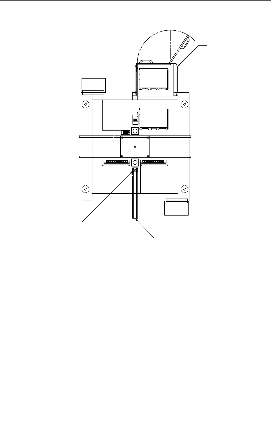
3.2 Installation Position
3.2 Installation Position
Recycle Conveyor B
Component Storage Box
(Small) B
Multi-Layer Tray Feeder
(Option)
(Front Side of Machine)
Fig. 2 Top View