故障排除Troubleshooting.pdf - 第15页
Page 13 IM T r oubleshooting 52489101 Rev . B This document supports Radial 88, VCD Seq 88, and Jumper Wire 88 machines. Troubleshooting Table - Insert Errors The following table lists possible error scenarios for insert…
Page 12
52489101 Rev. B IM Troubleshooting
This document supports Radial 88, VCD Seq 88, and Jumper Wire 88 machines.
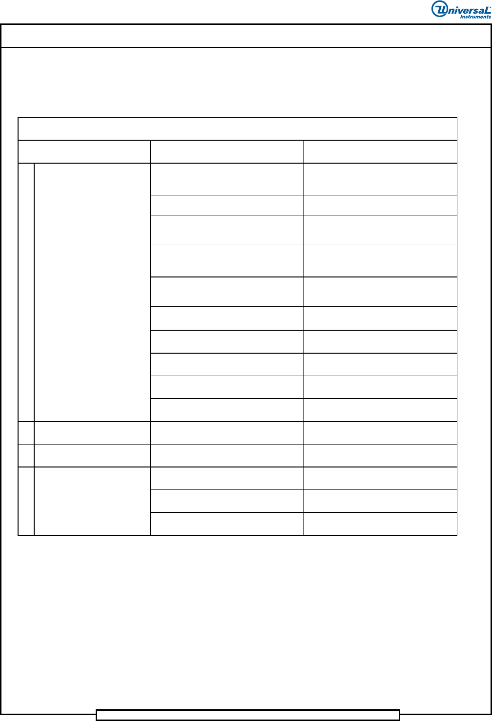
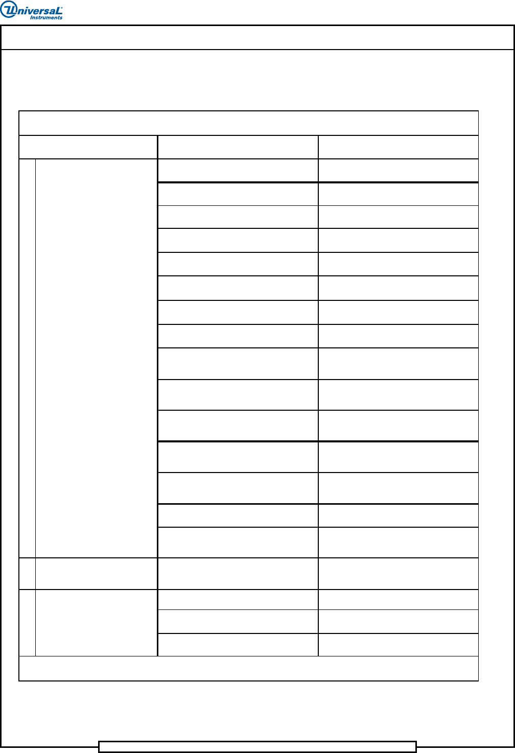
Troubleshooting Table - Span Axes System (VCD and
Jumper Wire Only)
The following table lists possible error scenarios for the span axes system.
Probable Cause Corrective Action
Loss of 230VAC to drive. Refer to electrical system table.
Relays HP1-1CR and HPI-2CR failed to
function.
Check for faulty relays or 24VAC per
electrical system table.
Servo amplifier circuit breaker not on.
Set circuit breaker to on. If circuit
breaker does not stay on, refer to
electrical system table.
Filter HP1-1FIL failed. Replace faulty filter.
Servo amplifier module failed.
Check status codes of module and
correct. Refer to Servo Chassis
Assembly procedures document.
Motion control board failed.
Refer to maintenance procedures and
replace motion control board.
Faulty drive motor. Replace motor.
Faulty encoder. Replace encoder.
Faulty wiring. Repair or replace faulty wiring.
Mechanical binding.
Lube, repair or replace faulty
mechanism.
2 Insert errors are occurring.
Debris between tooling housings or
anvils hindering movement.
Clean surfaces of lead screws between
tooling housings or anvils.
3
Axis goes into limit error
during automatic processing.
Offset values plus coordinate values
exceed travel limit.
Check offsets and/or reprogram pattern
coordinates. Refer to IM-UPS manual.
Dirty/dry lead screws and bushings.
Clean and lubricate lead screws and
bushings.
Dirty/dry shafts between tooling
housings or anvils.
Clean and lubricate shafts between
tooling housings or anvils.
Worn shafts or bearings. Replace shafts or bearings.
Troubleshooting Table - Span Axes System
1
Either span axis does not
zero or position.
Span axis is noisy.4
Indicated Trouble
Page 13
IM Troubleshooting 52489101 Rev. B
This document supports Radial 88, VCD Seq 88, and Jumper Wire 88 machines.
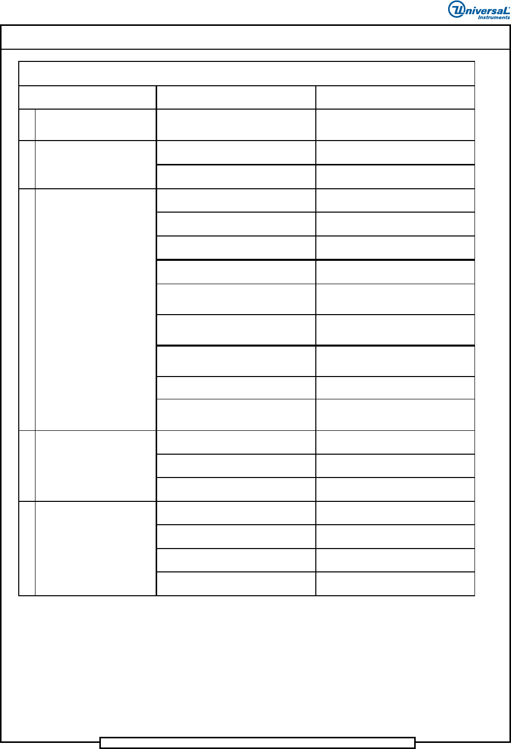
Troubleshooting Table - Insert Errors
The following table lists possible error scenarios for insert errors.
Probable Ca use Correc tive Action
Printed circuit board drilled incorrectly.
Replace out of tolerance printed circuit
boards.
Printed circuit board not properly located. Correct board location problem.
Pattern program coordinates are incorrect. Enter correct coordinates.
Machine zero setup out of tolerance (X, Y,
head, or clinch axes).
Refer to maintenance manual and set each
axis to specification.
Incorrect offset values. Enter correct offset values.
BEC setup out of tolerance.
Refer to maintenance section and set up
BEC.
Worn tooling. Replace worn tooling.
Bent or out of spec input.
Correct bad input. Refer to Component
Transfer Errors table.
VCD O nly:
Centering mechanism out of adjustment.
Refer to maintenance section and adjust
centering mechanism.
VCD and Radial Only:
Incorrect component loaded in dispensing
head.
Load dispensing head with correct
component.
Radial Only:
Poor transfer of component from
com
p
onent transfer assembl
y
to head.
Set up component transfer assembly per
maintenance manual.
Radial Only:
Incorrect dispensing head alignment/setup.
Set up and align dispensing head per
maintenance manual.
Radial Only:
Insert head jaws sluggish or out of
ali
g
nment.
Perform preventive maintenance, set up,
and align insert head jaws per
maintenance manual.
Radial Only:
Defective carrier clip spring or clamp.
Repair or replace as necessary.
Radial Only:
Insertion tooling clamp worn or spring
fati
g
ued.
Repair or replace as necessary.
2
VCD and Jump er Wire Only:
Machine does not detect insert
errors.
Continuity error failure.
Refer to the Clinch Assembly table in this
document.
Clinch malfunction. Refer to Clinch Assembly table.
Continuity circuit problem. Debug continuity circuit.
Clinch setup inco rrect/clinch is dirty.
Perform clinch preventive maintenance per
maintenance manual.
Continu ed on next pag e…
Troubleshooting Table - Insert Errors
Component leads do not enter
printed circuit board.
1
3
Machine reports insert errors
when inserts are good.
Indicated Trouble
Page 14
52489101 Rev. B IM Troubleshooting
This document supports Radial 88, VCD Seq 88, and Jumper Wire 88 machines.
Probable Ca use Correc tive Action
4
Component not centered. Centering mechanism out.
Refer to maintenance section and adjust
centering mechanism or replace centering
inserts.
Shorted or jammed clinch.
Perform clinch preventive maintenance per
maintenance manual.
Switches not set correctly or/failed Multi
Input I/O card.
Set switches per PC Jumper
Config/Replace Multi Input I/O card.
Printed circuit board is not drilled correctly.
Replace out of tolerance printed circuit
boards.
Printed circuit board is not properly
located.
Correct board location problem.
Defective carrier clip spring or clamp. Repair or replace as necessary.
Pattern program coordinates are incorrect. Enter correct coordinates.
Radial Only:
Incorrect component loaded in dispensing
head.
Load dispensing head with correct
component.
Radial Only:
Poor transfer of component from
com
p
onent transfer assembl
y
to head.
Set up component transfer assembly per
maintenance manual.
Radial Only:
Incorrect dispensing head alignment/setup.
Set up and align dispensing head per
maintenance manual.
Radial Only:
Insert head out of alignment.
Set up and align insert head jaws per
maintenance manual.
Radial Only:
Insertion tooling clamp worn or spring
fati
g
ued.
Repair or replace as necessary.
Clinch is jammed. Clear clinch jam.
Clinch height is set too low.
Adjust clinch height per maintenance
manual.
Head to clinch alignment is not correct. Adjust alignment per maintenance manual.
Clinch height is set too low.
Adjust clinch height per maintenance
manual.
Head to clinch alignment is not correct. Adjust alignment per maintenance manual.
Head to circuit board clearance is not set
prop erly.
Adjust head height per maintenance
manual.
Radial Only:
Pusher tip height is incorrect.
Ensure pusher tip is installed properly.
Troubleshooting Table - Insert Errors
, continued
Indicated Trouble
6
One Component lead does not
enter printed circuit board
5
Machine fails to report insert
errors
Component leads are not cut
and clinched
7
8
Component leads are too long
after cut and clinch