故障排除Troubleshooting.pdf - 第4页
Page 2 52489101 Rev . B IM T roubleshooting This document supports Radial 88, VCD Seq 88, and Jumper Wire 88 machines. • Machine Operation Guide CAUTI ON When performing troubleshooting procedures on machine electronics,…

Page 1
IM Troubleshooting 52489101 Rev. B
This document supports Radial 88, VCD Seq 88, and Jumper Wire 88 machines.
Functional Description
This document provides troubleshooting information for the electrical and
mechanical parts of the following machines:
• Radial 88
• VCD Seq 88
• Jumper Wire 88
Troubleshooting Concept
The troubleshooting procedures in this module identify specific maintenance
requirements to be used when performing maintenance on the machine. Refer
to the specific assembly support document for detailed information
pertaining to the procedures presented.
Troubleshooting
The purpose of this section is to provide the maintenance technician with
information on how to troubleshoot the insertion machine.
Troubleshooting is the process of evaluating a fault condition and isolating
the condition to a cause.
The cause may be evident by the physical condition of the machine and the
point in the operational cycle where the machine malfunctioned.
Where the cause is not evident, various troubleshooting techniques, presented
in this section, should be followed to determine the specific area and/or
component that caused the malfunction.
The insertion machine contains various features that are intended to assist the
technician in the troubleshooting procedure. These elements include the IM
Diagnostics functions, the pneumatic valve actuators, and the troubleshooting
tables.
Before performing the troubleshooting techniques, ensure that the following
criteria have been met.
1. The maintenance technician understands the sequence of events. Refer
to the Machine Operation Guide.
2. The correct pattern programs are resident and the correct program
selected. Refer to the following manuals:
• IM-UPS Reference Manual
• IM Diagnostics Reference Manual
Page 2
52489101 Rev. B IM Troubleshooting
This document supports Radial 88, VCD Seq 88, and Jumper Wire 88 machines.
• Machine Operation Guide
CAUTION
When performing troubleshooting procedures on machine electronics,
wear a wrist strap connected to ground to prevent electrostatic
discharge (ESD) damage to printed circuit boards and encoders.
WARNING
Do not adjust electrical switches or assemblies so that they actuate
switches unless the Emergency Stop switch on the machine is pushed
down or unless the procedure specifically says to have the Emergency
Stop switch released. Failure to press the Emergency Stop switch
before adjusting a switch or moving an assembly to actuate a switch
might result in personal injury.
Troubleshooting Techniques
The following troubleshooting techniques provide various methods for
isolating machine problems.
IM Diagnostics
The IM Diagnostics technique allows the user to display machine operational
feedback on the operator interface. Passive and active diagnostics routines
are available.
Passive diagnostics allows the user to determine the status of the controller
and each machine function that is input or output from the controller.
Refer to the IM Diagnostics Manual for detailed information on how to
perform diagnostics.
The machine IM diagnostics supplies a clear description of the machine
condition. This information is accessed through the operator interface, while
accessing various screens that allow machine interaction and informational
feedback.
Machine JOG Mode
The JOG mode allows machine operation to be manually controlled.
Incremental steps are executed, one function at a time, each time the Jog
button is selected in IM Diagnostics. In this manner, each function can be
observed as it occurs allowing the cause of a specific problem to be more
easily determined.
Page 3
IM Troubleshooting 52489101 Rev. B
This document supports Radial 88, VCD Seq 88, and Jumper Wire 88 machines.
Pneumatic Valve Actuators
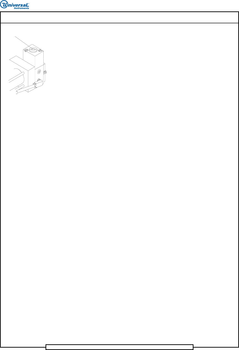
Plunger
Each pneumatic valve contains a plunger that allows the user to manually
actuate the valve. Actuating the valve in this manner assists in determining
whether the pneumatics or electrical controls are the cause of a specific
problem. If a valve does not operate, and pushing the plunger causes the
valve to operate, an electrical problem exists. If the valve fails to operate
when the plunger is pushed, a pneumatic or mechanical problem exists.
Troubleshooting Tables
The troubleshooting tables are another technique that gives the technician a
place to start. Some of the tables are symptom driven while other tables or
items within tables require that the technician first isolate the functional
problem to an assembly. After isolating the functional problem, use the
appropriate machine drawings to further troubleshoot the machine to a
specific component malfunction and then repair. For repairs requiring
adjustments or setup procedures, refer to the Maintenance Manual.
Machine Sequence of Events
The insertion machine dispenses leaded components from taped input
packages then inserts the components to a programmed location and
orientation in a printed circuit board.
The general sequence of events for the insertion cycle of the insertion
machine is as follows.
1. The feeders, located on the sequencer modules, remove the axial
leaded components from the input packages.
2. The feeders place the components in a programmed sequence on the
sequencer chain. The refire function will continue to fire the head a
programmed number of times to ensure a component is in place when
gaps in the presequenced tapes are encountered.
3. The sequencer chain transports the components to the insertion chain
clips.
4. The insertion chain clips transport the components to the missing part
sensor, centering assembly, and then to the insertion head tooling.
5. As the components are being transported to the insertion tooling, a
board is positioned to the programmed coordinates for component
insertion.
6. Component presence is checked at the missing part sensor and correct
component value is verified at the optional verifier assembly. If either
operation fails to meet programmed specifications, a repair function
allows the operator to correct the condition.